Clogging detector for air filter

a detector and filter technology, applied in the direction of machines/engines, instruments, separation processes, etc., can solve the problems of increasing pressure differential, not applicable to larger spaces, and not being useful in small compartments of motor vehicles

Active Publication Date: 2007-02-20
CLEAN ALERT
View PDF4 Cites 46 Cited by
  • Summary
  • Abstract
  • Description
  • Claims
  • Application Information

AI Technical Summary

Problems solved by technology

This method while useful for small compartments in motor vehicles, isn't applicable to larger spaces, like houses, due to a negligible variations in the air blower response.
It is seen that with the increased clogging, the air flow resistance of the filter increases and that, in turn, results in the increased pressure differential.
This method while efficient from the performance stand point, is relatively expensive and may pose difficulties in practical use: in many existing air supply and re-circulating systems installation of the tubes at both sides of an air filter may be difficult if not impractical due to the equipment geometry.
Besides, quite often small pressure levels would requires a sensitive (thus more expensive) pressure sensor.
An obvious disadvantage of this method of detection is its dependence on the type of airborne contaminants.
Besides, the light emitter and detector may become clogged themselves.
All the above methods are either time consuming, or too complex and costly, or simply not sensitive enough for detecting the filter clogging for a multiplicity of the filter and air blower configurations.

Method used


Image

  • Clogging detector for air filter
  • Clogging detector for air filter
  • Clogging detector for air filter

Examples


Embodiment Construction

[0043]Air Heating and Conditioning Applications

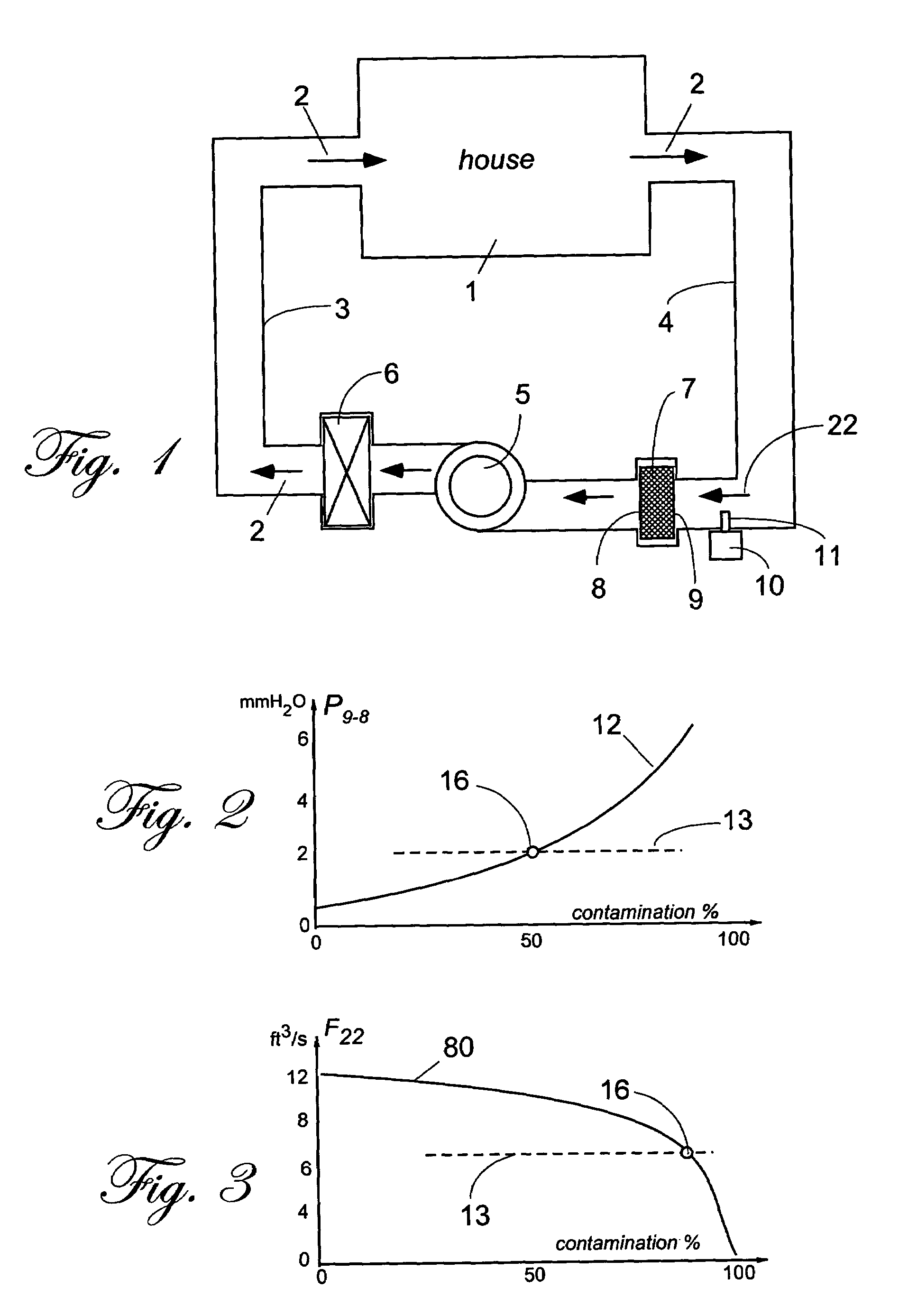
[0044]FIG. 3 illustrates what typically happens with the air flow rate 80 when the air filter collects more and more contaminants. When the filter is clean or soiled a little, it exhibits a relatively small air flow resistance and the air flow is at its maximum. When the filter collects more and more dirt, the air flow rate drops approaching zero when the filter becomes completely clogged. Threshold 13 may be set to indicate a critically reduced air flow rate at point 16. It should be noted that threshold 13 may have not a fixed but rather a variable value. The value may be controlled by signals that indicate variations in the air supply characteristics, such as temperature and an air blower power or rotation rate.

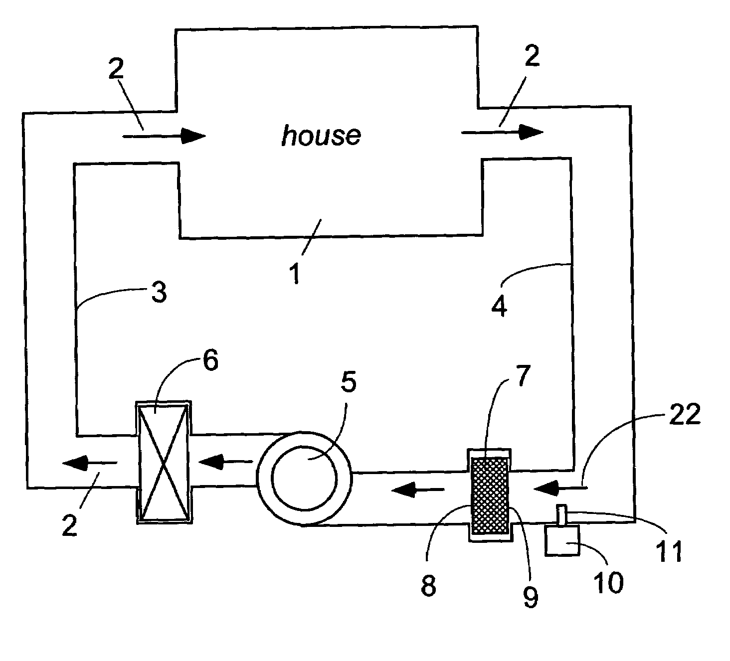
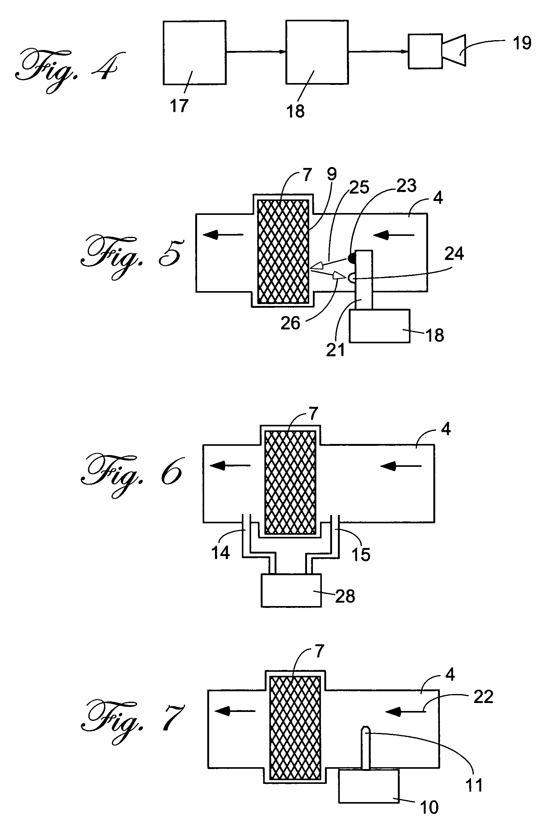
[0045]FIG. 7 shows an air flow rate sensor installed into return duct 4 upstream from filter 7. Air flow rate probe 11 may be of several designs. For example, it may have a rotating vane, tilted vane, and many other designs kn...


PUM

PropertyMeasurementUnit
timeaaaaaaaaaa
poweraaaaaaaaaa
flow rateaaaaaaaaaa

Abstract

The detector for monitoring decrease in air flow rate due to air filter clogging. It is based on combination of three essential components: the air flow sensor, a threshold detector and an indicator. The air flow sensor is built in form of a novel thermo-anemometer which contains a thermistor, a heating element, and a thermal insulator. Temperature of the sensor is maintained above the air temperature by a constant value by means of an electronic servo circuit. The threshold detector is implemented either in a hardware or software. A novel design of a thermo-anemometer (closely related to a hot wire anemometer) automatically compensates for variations in the air temperatures. The thermo-anemometer triggers the threshold circuit when air flow rate drops below a preset level. For reduction of power consumption, the detector may employ two additional sensors: one is for detection of the blower operation and the other is a presence detector to enable the alarm in presence of people to perceive the alarm. The device automatically calibrates itself upon installation of a new or cleaned air filter. The applications include residential and commercial air conditioners, air heaters, internal combustion engines, vacuum cleaners and other systems where air filters are employed.

Description

[0001]The present invention relates generally to devices for monitoring a functional state of equipment, and more particularly to a device for detecting a degree of clogging of a gas (air, e.g.) filter and producing a signal indicating the same. This patent is based on U.S. Provisional Patent Application No. 60 / 555,011 filed on Mar. 22, 2004.BACKGROUND OF INVENTION[0002]Nearly every residential and industrial dwelling or facility, an automobile with an internal combustion engine, or a vacuum cleaner incorporates some kind of an air supply or air treatment system. These systems range from a simple ventilation duct to automatic air conditioning installations that may include heating, cooling and humidity control devices. Typically, mass of gas (air, in particular) is driven through the dwelling or machinery by means of a forced convection. This requires use of a pump or air blower. Also, they usually include filtration components (filters). The purpose of the filters is to remove airb...

Claims


Application Information

Patent Timeline
Patent Type & Authority Patents(United States)
IPC IPC(8): G01F1/37
CPCA47L9/19B01D46/0086G01F1/696B01D46/46B01D46/448F24F2011/0093F24F11/39
Inventor FRADEN, JACOBRUTSTEIN, ALEX
Owner CLEAN ALERT
Why Eureka
Try Eureka