Ring gear

a ring and gear technology, applied in the field of ring gear, can solve the problems of inability to create longitudinally cambered tooth flanks, limit the design of the rounding of the tooth base, etc., and achieve the effects of simple and fast adjustment, high precision and replicability, and economics

Inactive Publication Date: 2007-02-20
ROBERT BOSCH GMBH
View PDF21 Cites 18 Cited by
  • Summary
  • Abstract
  • Description
  • Claims
  • Application Information

AI Technical Summary

Benefits of technology

[0009]It is proposed that the tooth flanks, after a final engagement point of the pinion, from the tooth head toward the tooth base, compared to standard tooth flanks, are made to approximate a trochoid, described by the pinion and projected into a normal section. By this means, lever arms by way of which forces act on the teeth can be shortened; at a cross section of the tooth that is at risk of breakage, a long radius can be attained, thus increasing the load-bearing capacity and lengthening the service life. The term “standard tooth flanks” should be understood to mean flanks of a ring gear that correspond to involute flanks.
[0017]Because of the CNC control, high precision and replicability can be achieved, so that it is possible to produce stamping tools and electrodes with high-precision teeth. The CNC milling machine is also simple and fast to adjust, compared to a bevel-gear rolling-milling machine or bevel-gear planing machine.

Problems solved by technology

However, longitudinally cambered tooth flanks cannot be created by this process.
In typical rolling methods, such as by means of milling or planing, longitudinally cambered tooth flanks can indeed be produced, but limits are placed on the design of the rounding of the tooth base.

Method used


Image

  • Ring gear
  • Ring gear
  • Ring gear

Examples


Embodiment Construction

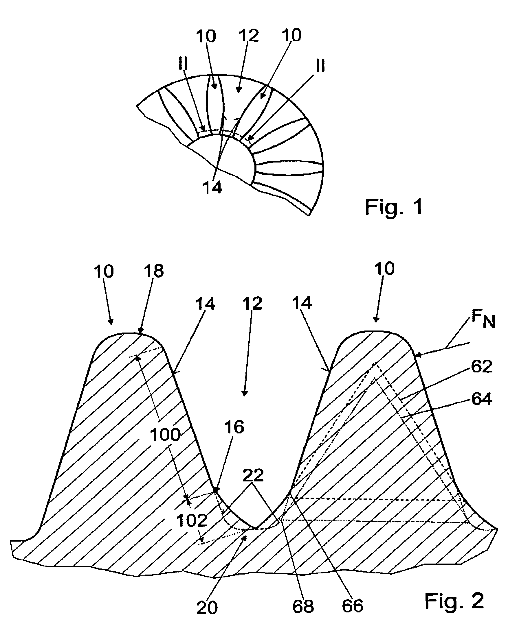
[0027]FIG. 1 shows a detail of a schematic plan view of a ring gear of the invention, with teeth 10 and tooth gaps 12; the teeth 10 can be brought into engagement with a corresponding pinion, not shown in detail here, by way of tooth flanks 14.

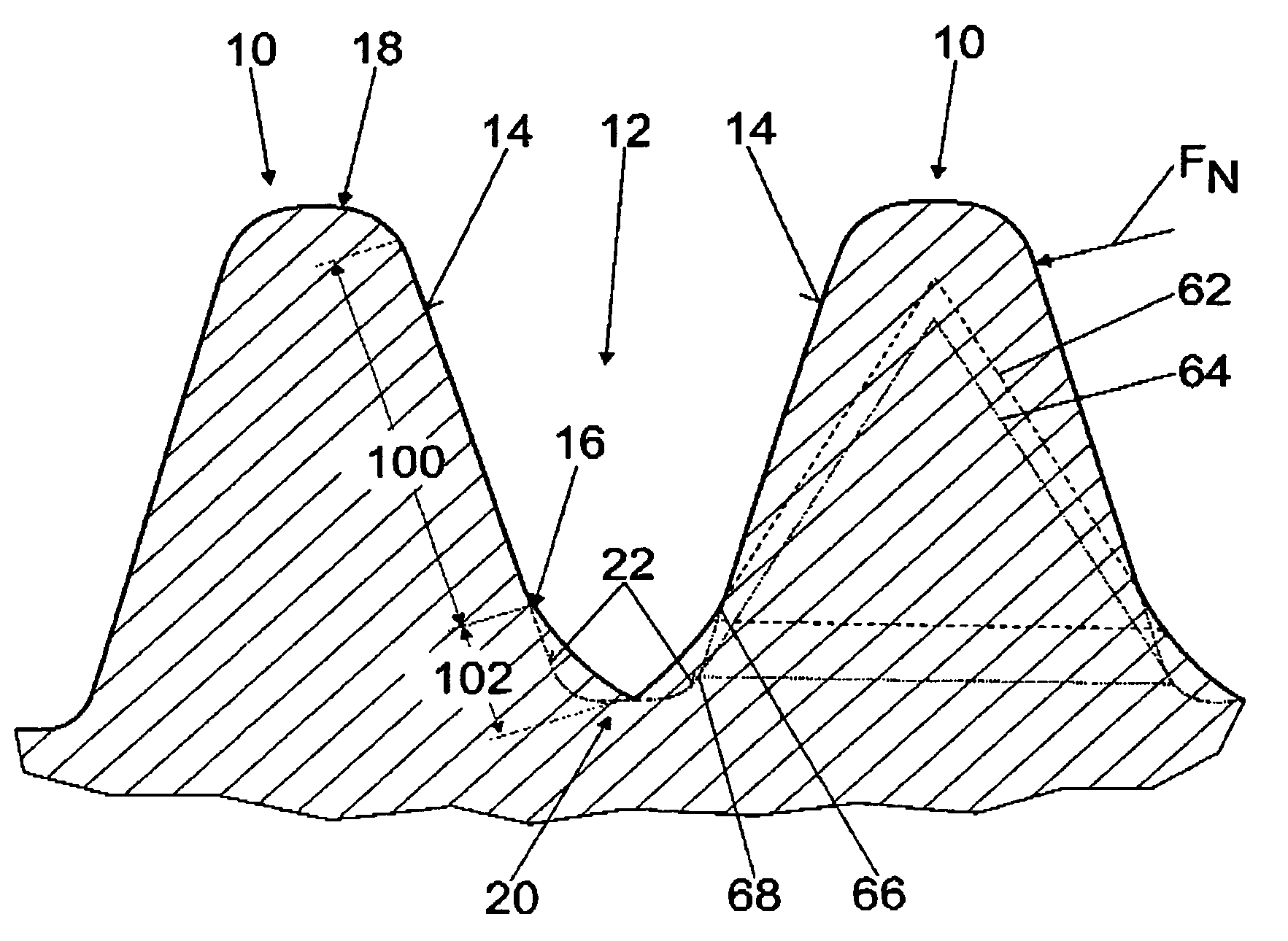
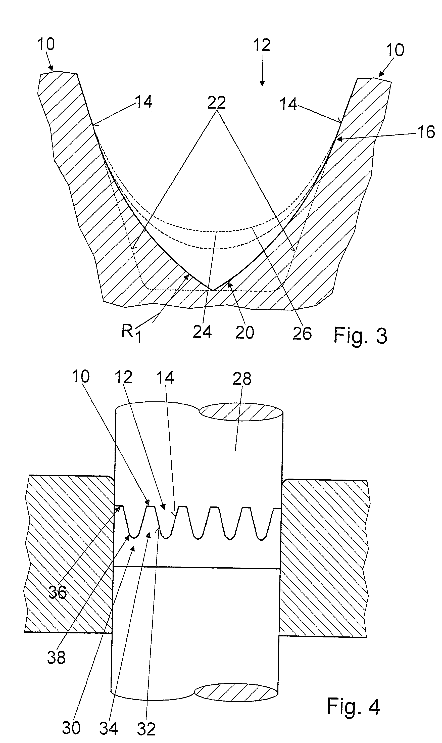
[0028]The tooth flanks 14, after a final engagement point 16 of the pinion, from the tooth head 18 toward the tooth base 20, compared to standard tooth flanks 22, are made to approximate a trochoid 24, 26, described by the pinion and projected into a normal section; specifically, the tooth gap 12 is embodied in the form of a pointed arch in cross section in the region of the tooth base 20 (FIGS. 2 and 3).

[0029]The trochoid 24 is described by a pinion with a rated tooth height, and the trochoid 26 is described by a pinion with a rated tooth height plus 0.1 mm. The tooth flanks 14, after the last engagement point 16 in the direction of the tooth base 20, have a radius R1 of approximately 1.6 mm and before the engagement point 16 from the tooth h...


PUM

PropertyMeasurementUnit
heightaaaaaaaaaa
radius R1aaaaaaaaaa
radius R2aaaaaaaaaa

Abstract

A ring gear includes teeth (10) and tooth gaps (12), in which the teeth (10) can be brought vie tooth flanks (14) into engagement with a corresponding pinion. The tooth flanks (14), after a final engagement point (16) of the pinion, from the tooth head (18) toward the tooth base (20), compared to standard tooth flanks (22), are made to approximate a trochoid (24, 26), described by the pinion and projected into a normal section.

Description

CROSS-REFERENCE[0001]The invention described and claimed hereinbelow is also described in PCT / DE 02 / 01636, filed on May 7, 2002 and DE 101 25 067.3, filed May 23, 2001. This German Patent Application, whose subject matter is incorporated here by reference, provides the basis for a claim of priority of invention under 35 U.S.C. 119 (a)–(d).BACKGROUND OF THE INVENTION[0002]The invention is based in particular on a ring gear.[0003]In principle, the goal is to furnish ring gears and pinions that correspond with the ring gears that assure a long service life and quiet meshing.[0004]In production, the goal is to replace metal-cutting production methods that as a rule are cost-intensive, with economical noncutting production methods, and sintering gains high significance.[0005]A stamping tool that can be used for sintering has a negative form of a set of teeth of the ring gear or pinion, as applicable, to be made, and is advantageously produced with an electrode.[0006]Suitable electrodes a...

Claims


Application Information

Patent Timeline
Patent Type & Authority Patents(United States)
IPC IPC(8): F16H55/17B23F5/20B22F5/08B23F1/06F16H55/08
CPCB22F5/08B23F1/06F16H55/0846Y10T74/19963Y10T29/49462Y10T74/19958
Inventor BARTH, WALTER
Owner ROBERT BOSCH GMBH
Why Eureka
Try Eureka