Hybrid vehicle

a hybrid vehicle and hybrid technology, applied in the direction of fluid gearings, external condition input parameters, braking components, etc., can solve the problems of limiting the improvement of running performance, drivability or riding comfort,

Inactive Publication Date: 2007-02-20
TOYOTA JIDOSHA KK
View PDF75 Cites 25 Cited by
  • Summary
  • Abstract
  • Description
  • Claims
  • Application Information

AI Technical Summary

Benefits of technology

[0010]A main object of the present invention is to provide a hybrid vehicle which can exploit, during one prime mover is active, the output of another prime mover effectivel...

Problems solved by technology

However, what is done by the hybrid vehicle disclosed in the aforementioned Laid-Open is only to assist the shortage of the drive force of the engine or the b...

Method used


Image

  • Hybrid vehicle
  • Hybrid vehicle
  • Hybrid vehicle

Examples


first control example

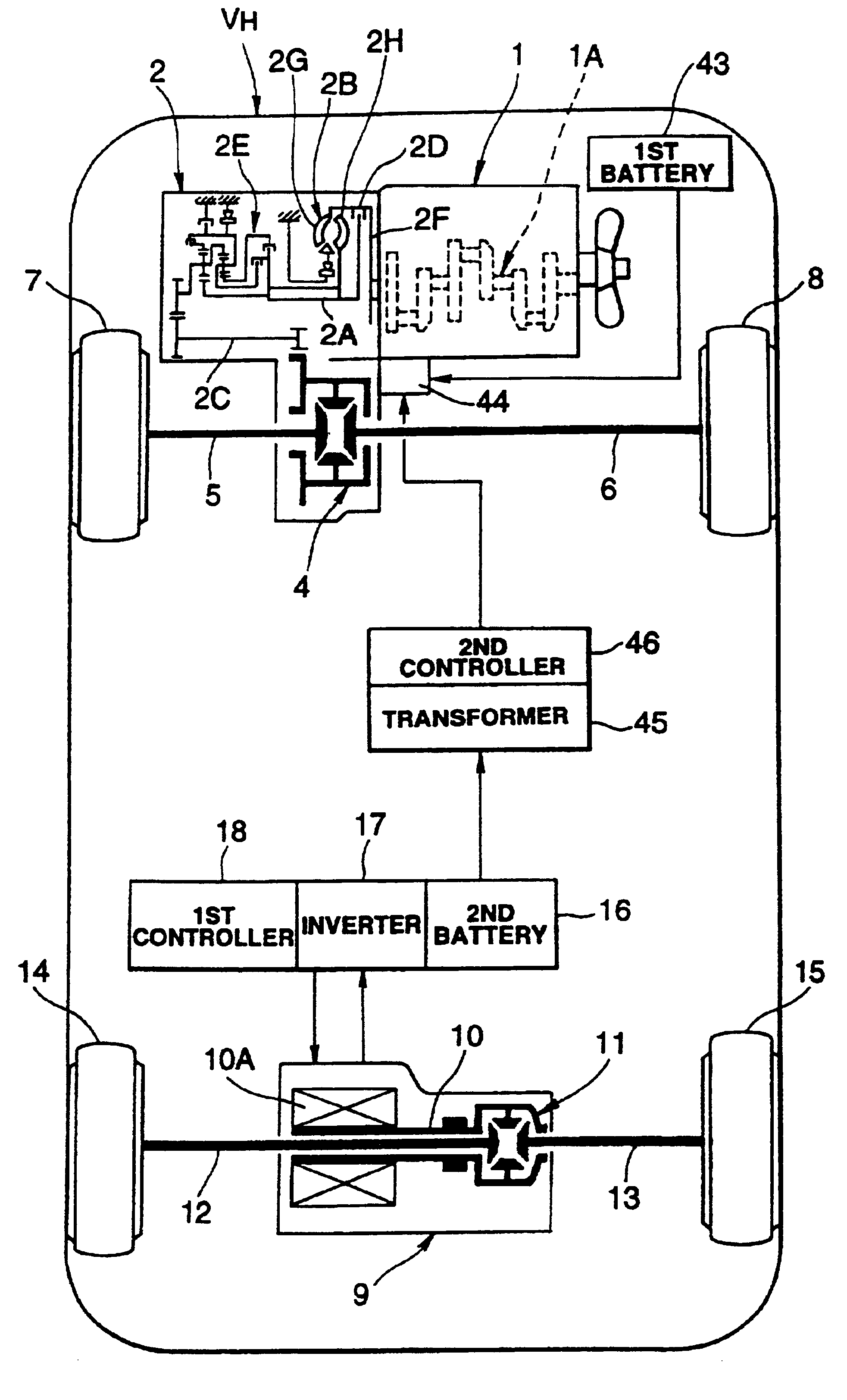
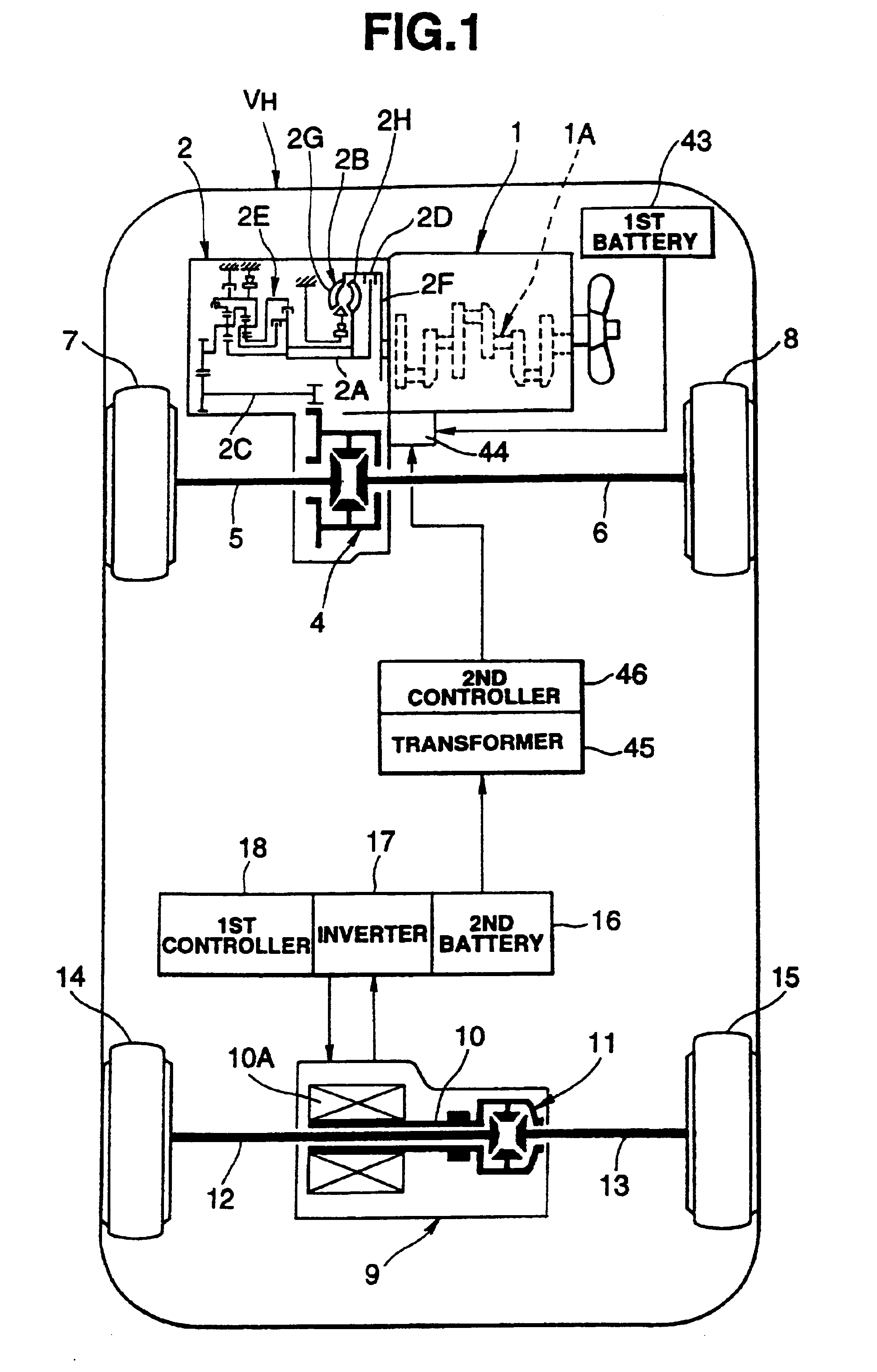
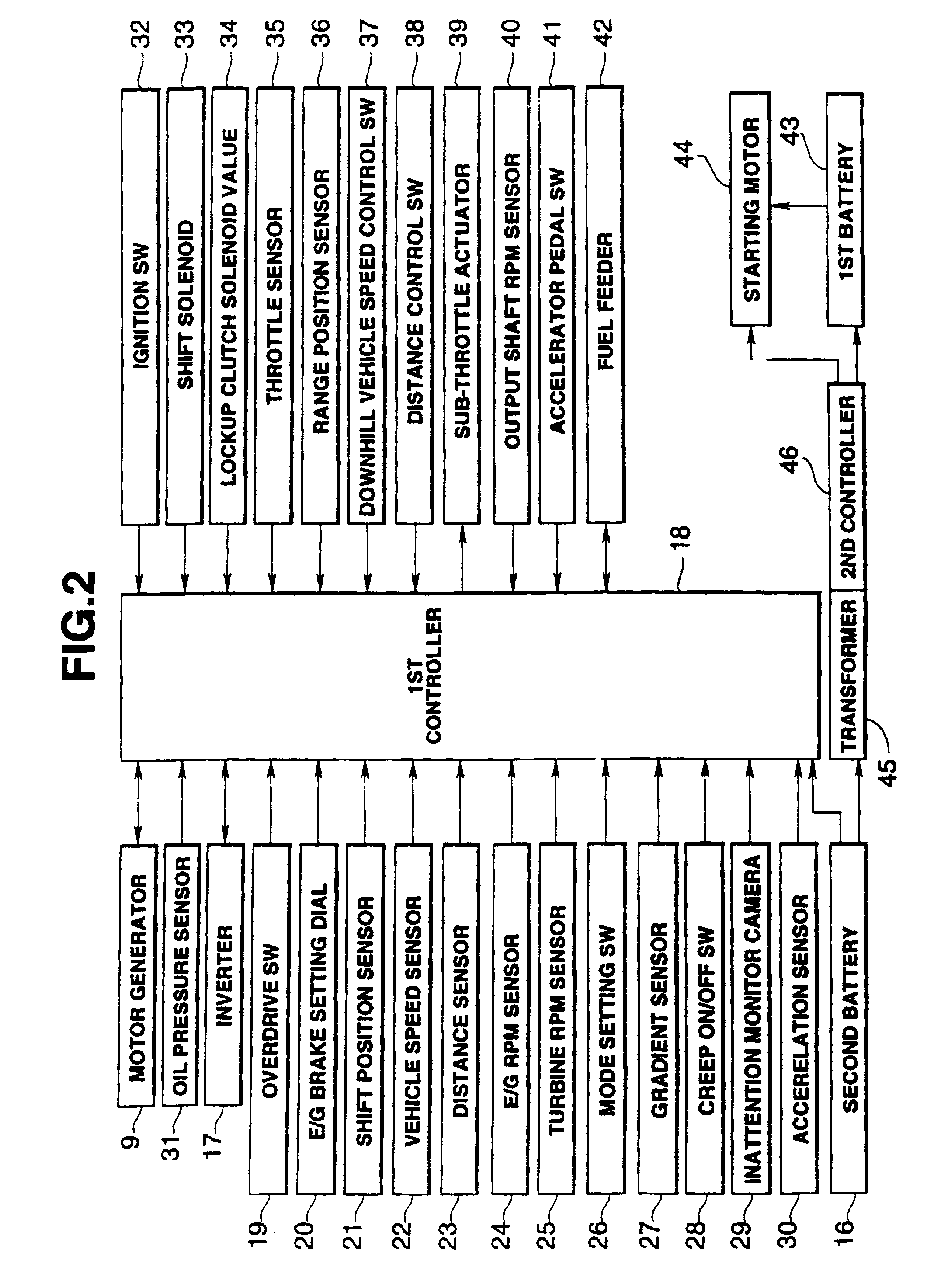
[0099]A control example corresponding to the first characteristic construction will be described with reference to the flow chart of FIG. 3. First of all, while the hybrid vehicle HV is running, it is decided (at Step 1) by the first controller 18 whether or not the range position of the automatic transmission 2 is in a D (drive) range. If the answer of Step 1 is “YES”, it is decided (at Step 2) by the first controller 18 whether or not the automatic transmission 2 is shifted up to the highest gear stage, that is, whether or not the vehicle is running at a high speed.

[0100]If the answer of Step 2 is “YES”, it is decided (at Step 3) by the first controller 18 whether or not the throttle valve opening of the engine 1 (as will be shortly referred to the “throttle opening”) θ is 0, that is, whether or not the power is OFF (in the idling state). If the answer of Step 3 is “YES”, it is meant that the driver has an intention to decelerate the vehicle so that the engine braking force is est...

second control example

[0106]FIG. 4 is a flow chart showing another control example corresponding to the first characteristic construction. First of all, while the hybrid vehicle HV is running, it is decided (at Step 11) by the first controller 18 whether or not the overdrive switch 19 is OFF. If the answer of Step 11 is “NO”, the running state is to establish no engine braking force, i.e., to have no demand for the braking, and the routine is returned. Incidentally, this decision can be made even if the D-range, the second range or the L-range is selected in the automatic transmission 2.

[0107]If the answer of Step 11 is “YES”, that is, if the braking is demanded, it is decided (at Step 12) by the first controller 18 whether or not the automatic transmission 2 is at a gear stage next to the highest one, i.e, at a gear stage for establishing the engine braking force. If the answer of Step 12 is “YES”, that is, if the demand for the braking is made, the routine advances to the controls of Steps 13 to 18. Th...

third control example

[0110]FIG. 5 is a flow chart showing another control example corresponding to the first characteristic construction. In this control example, while the hybrid vehicle HV is running, it is decided (at Step 21) by the first controller 18 whether or not the downhill vehicle speed control switch 37 is ON. If the answer of Step 21 is “YES”, it is decided (at Step 22) by the first controller 18 whether or not the engine 1 is idling (with power OFF), i.e., demanded for the braking.

[0111]If the answer of Step 22 is “YES”, the engine braking force is established by the engine 1, and the first controller 18 stores the vehicle speed V0 at the power OFF (at Step 23). Then, it is decided (at Step 24) whether or not the vehicle speed V is over the value V0 after a predetermined time period from controlling at Step 23. This decision is made, as based upon whether or not the hybrid vehicle HV is running downhill so that it cannot be decelerated by the engine braking force.

[0112]If the answer of Ste...


PUM


Abstract

A hybrid vehicle having an engine and a motor to be controlled independently of each other for running the vehicle. This hybrid vehicle is given a braking demand detecting function to detect a braking demand through an idle ON of the engine while the vehicle is running, and a first braking function to suppress the rise in the vehicle speed of the vehicle by a regenerative braking force of the motor if the braking demand is detected by the braking demand detecting function.

Description

BACKGROUND OF THE INVENTION[0001]1. Field of the Invention[0002]The present invention relates to a hybrid vehicle equipped with a plurality of prime movers for running the vehicle.[0003]2. Related Art[0004]In the prior art, there have been developed a hybrid vehicle which is intended to improve an overall efficiency by combining a plurality of prime movers while exploiting the merits and compensating the demerits of the individual prime movers. One example of this hybrid vehicle is disclosed in JPA-7-186748.[0005]The hybrid vehicle, as disclosed, is equipped with an engine and a motor-generator as the prime movers. The motor-generator is given a power running function to convert an electric energy into a kinetic energy, and a regenerative function to establish a regenerative braking force by converting a kinetic energy into an electric energy.[0006]Moreover, the hybrid vehicle is constructed such that the drive force of the engine is transmitted either the front wheels or the rear w...

Claims


Application Information

Patent Timeline
IPC IPC(8): B60K6/00B60K17/04B60K1/00B60K1/04B60K6/20B60K6/48B60K6/52B60K6/543B60K6/547B60K17/356B60K23/08B60K31/00B60L7/22B60L15/20B60L50/15B60L50/16B60W10/06B60W10/08B60W10/10B60W10/18B60W20/00B60W30/18F16H59/08F16H59/38F16H59/46F16H59/68F16H59/70F16H59/72F16H61/04F16H61/14F16H61/20F16H61/21F16H63/40
CPCB60K6/48B60K6/52B60K6/547B60K17/356B60K31/0008B60W10/06B60W10/08B60W10/10B60W10/18B60W20/00B60W30/18127B60L7/14B60L11/126B60L11/14B60L11/1868B60L15/2009B60K1/04B60K23/0808B60T2270/603B60W2050/143B60W2520/10B60W2540/06B60W2540/22B60W2550/10B60W2550/142B60W2550/308F02D2200/501F16H59/68F16H59/70F16H59/72F16H61/14F16H61/20F16H61/21F16H63/40F16H63/502F16H2059/006F16H2059/385F16H2059/467F16H2059/6807Y02T10/6221Y02T10/6265Y02T10/6286Y02T10/6295Y10S903/903Y10S903/945Y10S903/917Y10S903/947Y10S903/916Y10S903/919B60L2240/12B60L2240/16B60L2240/36B60L2240/423B60L2240/441B60L2240/443B60L2240/68B60L2250/10B60L2260/28Y02T10/7077Y02T10/7005Y02T90/16Y02T90/161Y02T10/7066Y02T10/7275Y02T10/6217Y02T10/7291Y02T10/642B60L50/62B60L50/16B60L58/20B60W2552/15B60W2554/00B60W2554/801B60W2540/221Y02T10/62Y02T10/64Y02T10/70Y02T10/7072Y02T10/72B60W20/30B60W2554/802
Inventor MORISAWA, KUNIOOZEKI, TATSUYA
Owner TOYOTA JIDOSHA KK
Why Eureka
Try Eureka