
Device for supplying lubricant to several lubrication points on machine parts

a technology for lubricant supply and machine parts, which is applied in the direction of drip lubrication, lubricating pump, drip lubrication, etc., can solve the problems of affecting the accuracy with which lubricant is dispensed, and it is not possible to vary the number of lubrication points during this operation, so as to achieve the effect of precise supply of lubrican

Inactive Publication Date: 2007-02-20
PERMA TEC
View PDF5 Cites 4 Cited by
  • Summary
  • Abstract
  • Description
  • Claims
  • Application Information

AI Technical Summary

Benefits of technology

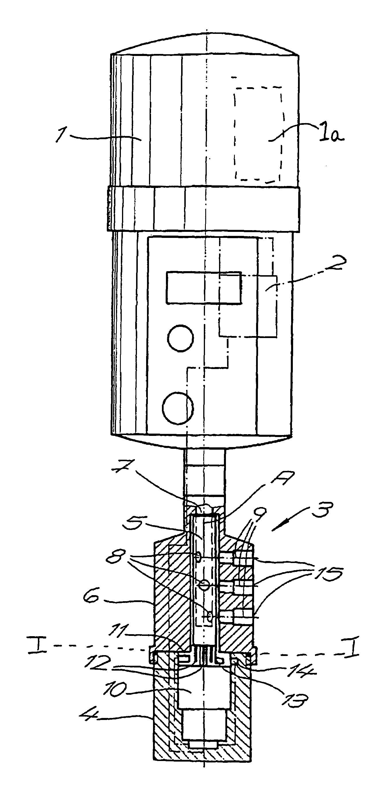
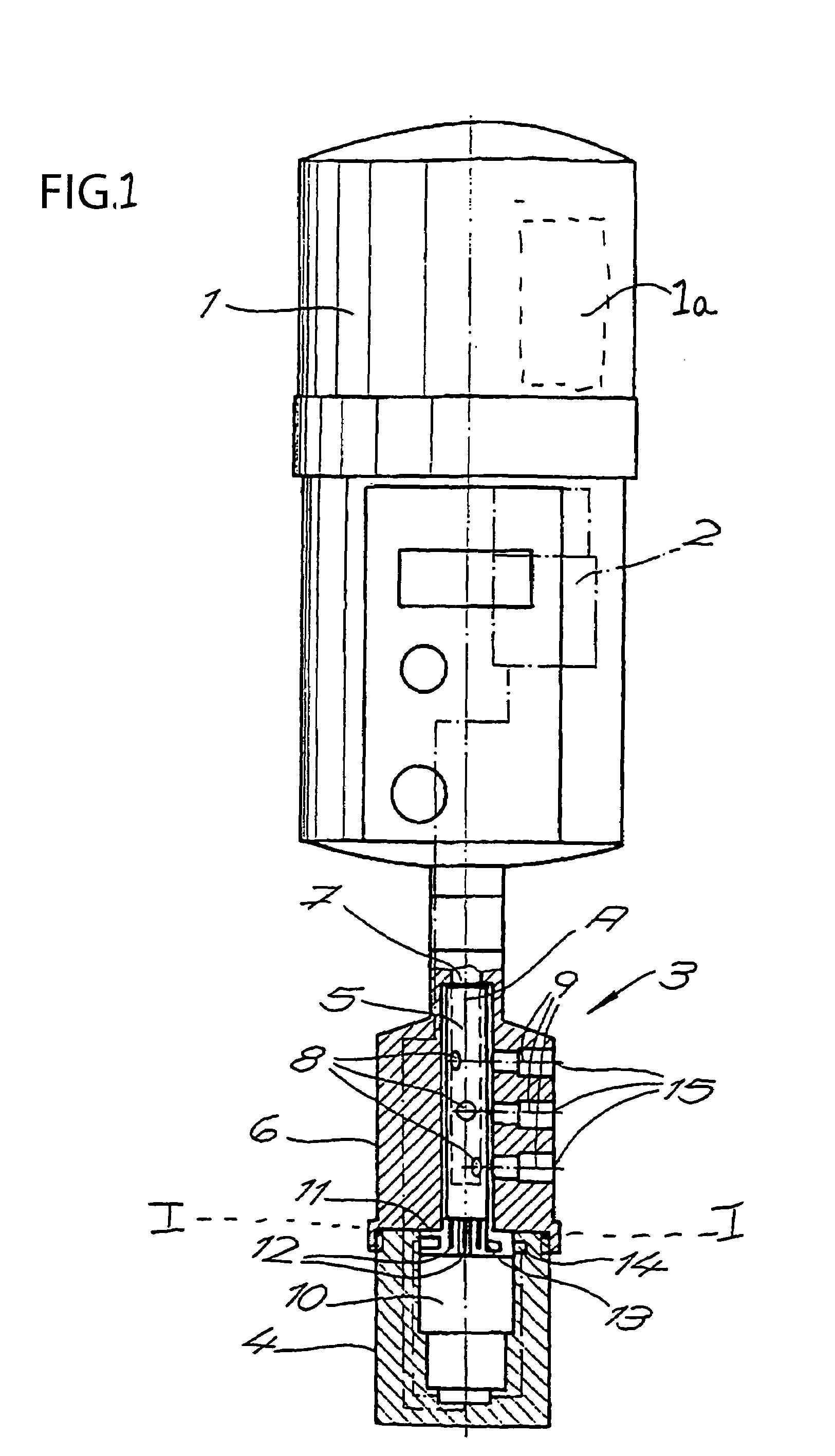
[0006]The task of the invention is accomplished by creating a device that relates to a distribution device that has an electric motor drive for changing the angle position of the distributor body. This electric motor can be controlled by the electronic control of the lubricant dispenser. In this design, the electric motor drive has a running path control that has a switch that functions electro-mechanically or in a contact free manner. The electric motor drive stops the rotational movement of the distributor body in different release angle positions that can be variably established. Thus, this design allows the flexible and at certain times, a precise supply of lubricant to different lubrication points. This is because the rotational movement of the distributor body is completely separated or uncoupled from the lubricant releases of the lubricant dispenser via this separate motor drive.
[0010]This design has the advantage that the lubricant release and the rotational movement of the distributor body do not occur simultaneously, but rather occur sequentially, one after the other. The release of this lubricant therefore occurs only if one of the distributor bores aligns with the opening bore assigned to it, and thereby uncovers this opening bore completely.
[0011]Therefore, during the release of the lubricant, there is no partial alignment between the two bores, they are instead completely aligned, which would bring about a clear increase in pressure loss in the distribution device. Thus, with this design, the amount of lubricant to be released can be very precisely metered.
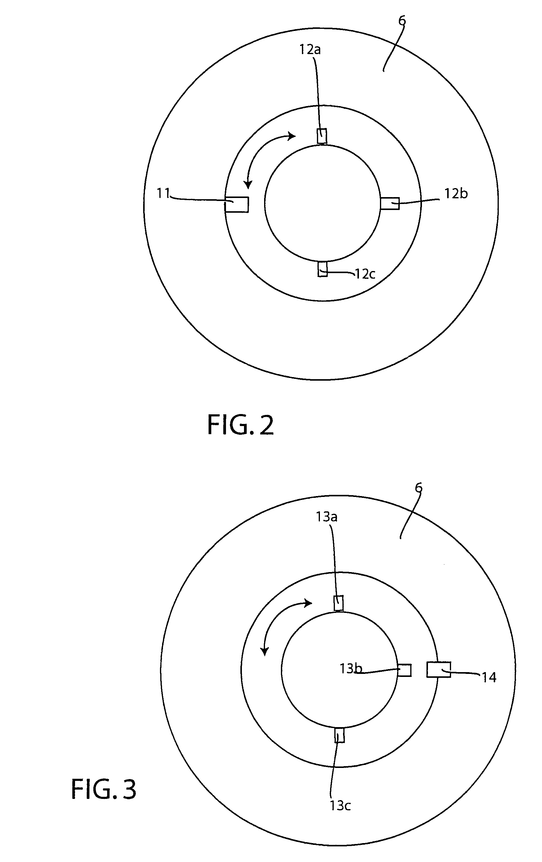
[0012]This distribution device can have a device for recognizing the exact release angle position, which gives off different signals assigned to the release angle positions. A first type device for determining the release angle position can be in the form of the position pins with a corresponding mechanical sensor that is triggered when it is contacted by the position pins. Another type device for determining a release angle position can be in the form of a coding wherein this coding is a non-contact form with a corresponding sensor. The sensor sends a unique signal value back to the electronic control of the lubricant dispenser. In this way, the electronic control of the lubricant dispenser recognizes what release angle position is present at all times. In addition this electronic motor drive can have a device for the detection of the angle of rotation that refers back to the reference value for the angle of rotation wherein the measurement values can be passed to the electronic control of the lubricant dispenser for further signal processing. Thus, with both the electric motor drive and the sensor system working together, the electric control can consistently monitor the angle of rotation of the distribution device.

Problems solved by technology

However, since the coverage of the distributor bores by the opening bores changes in this design, pressure variations occur, which have a detrimental effect on the accuracy with which the lubricant is dispensed.
In addition, in this arrangement, it is not possible to vary the number of lubrication points during this operation.

Method used


Image

  • Device for supplying lubricant to several lubrication points on machine parts
  • Device for supplying lubricant to several lubrication points on machine parts
  • Device for supplying lubricant to several lubrication points on machine parts

Examples


Embodiment Construction

[0020]Turning now in detail to the drawings, FIG. 1 is a side cross-sectional view of a first embodiment of the invention. In this device, there is a device for supplying several lubrication points on machine parts with lubricant. This device comprises an electromechanical lubricant dispenser 1 having a pump 1a for pumping the lubricant, an electrical control 2 for controlling the pumping of the lubricant and a distribution device 3 connected to a lubricant outlet of lubricant dispenser 1. Distribution device 3 has a housing 4, a cylindrical hollow distributor body or distribution tube 5 that is mounted to rotate about a vertical axis A. There is also a fixed cylindrical distributor sleeve 6 that surrounds distributor body 5 forming a seal. Distributor body 5 has an opening 7 at the top, for letting in the dispensed lubricant. Body or tube 5 has a plurality of distributor bores 8 on its circumference, which are offset axially relative to one another.

[0021]Each distributor bore 8 has...


PUM


Abstract

A device for supplying several lubrication points on machine parts with a lubricant, comprising an electromechanical lubrication dispenser and a distribution device coupled to a lubricant outlet of the dispenser. The distribution device has a housing, a cylindrical hollow distributor body or tube which is mounted to rotate about a vertical axis. There is also a fixed cylindrical sleeve that surrounds the distributor body, forming a seal. The distributor body has an opening at the top for allowing the lubricant in, and has at least two distributor bores disposed on the circumference but offset axially from one another. Each of these distributor bores has a corresponding opening bore in the distributor sleeve that is assigned to it. This distribution device also has an electric motor drive that has a running path control that has a switch that functions electromechanically or in a contact free manner. This drive has a switch that stops the rotational movement in different release angle positions that can be variably established.

Description

CROSS REFERENCE TO RELATED APPLICATIONS[0001]This Application hereby claims priority under 35 U.S.C. 119 from German Patent Application Serial no. 202 17 308.9 filed on Nov. 9, 2002.BACKGROUND OF THE INVENTION[0002]The invention relates to a device for supplying lubricant to several lubrication points on machine parts. This device comprises an electro-mechanical lubricant dispenser having an electric control which is used to control a distribution device. The distribution device is connected to a lubricant outlet of the lubricant dispenser and comprises a housing, a cylindrical hollow distributor body or tube mounted to rotate about a vertical axis, and a fixed cylindrical distributor sleeve that surrounds the distributor body forming a seal.[0003]In this case, the distributor body or distribution tube which has an opening at the top for allowing lubricant in, has at least two distributor bores on the circumference, offset axially form one another. Each of these bores has an opening...

Claims


Application Information

Patent Timeline
Patent Type & Authority Patents(United States)
IPC IPC(8): F01M11/04F16N11/08F16N25/04
CPCF16N25/04F16N11/08
Inventor WEIGAND, MICHAEL
Owner PERMA TEC
Learn More