High efficiency driver for color light emitting diodes (LED)

a technology of light-emitting diodes and driver, which is applied in the direction of electric variable regulation, process and machine control, instruments, etc., can solve the problems of high current power supply efficiency, low efficiency, and high resistance loss of high current, and achieve high efficiency, high efficiency, and low dissipation.

Active Publication Date: 2007-02-20
HONG KONG THE UNIV OF
View PDF14 Cites 12 Cited by
  • Summary
  • Abstract
  • Description
  • Claims
  • Application Information

AI Technical Summary

Benefits of technology

[0007]Apparatus and method for providing power to multiple light emitting diodes (LEDs), including those corresponding to the three primary colors, are disclosed. The apparatus provides an integrated solution to drive the three types of color LEDs by using the LED itself as a rectifying device in a switching power converter. Furthermore, the apparatus does not require a dissipative element, e.g., a linear driver resulting in energy efficient operation due to lower dissipation than known power supplies. Various embodiments of the invention provide simple non-isolated power conversion as well as isolated configuration for off-line operation. Consequently, known off-line power converter configuration such as forward and flyback converters are compatible with the disclosed apparatus. The brightness of each of the three colors can be modulated by a passive element, the duty cycle or the switching frequency resulting in a versatile and highly efficient power conversion apparatus with fewer components and smaller size than known designs.

Problems solved by technology

A drawback of low-voltage high current power supplies is their low efficiency.
Thus, voltage produced is shared between this diode and the LED and brings the efficiency down to nearly 50 percent with the high current producing high resistive losses.
However, this arrangement reduces reliability because the failure of any one of the LEDs in the series arrangement results in the failure of the whole arrangement.
However, this method is exhibits great power dissipation and low efficiency.
An arrangement with such low efficiency produces significant heat resulting in the need for a heat sink increasing product size while reducing reliability.

Method used


Image

  • High efficiency driver for color light emitting diodes (LED)
  • High efficiency driver for color light emitting diodes (LED)
  • High efficiency driver for color light emitting diodes (LED)

Examples


Embodiment Construction

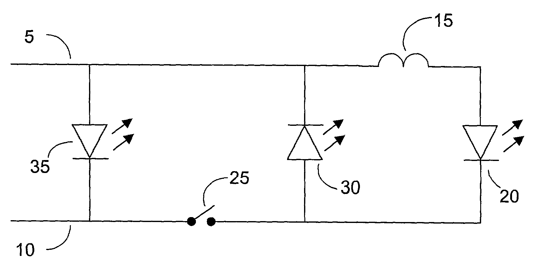
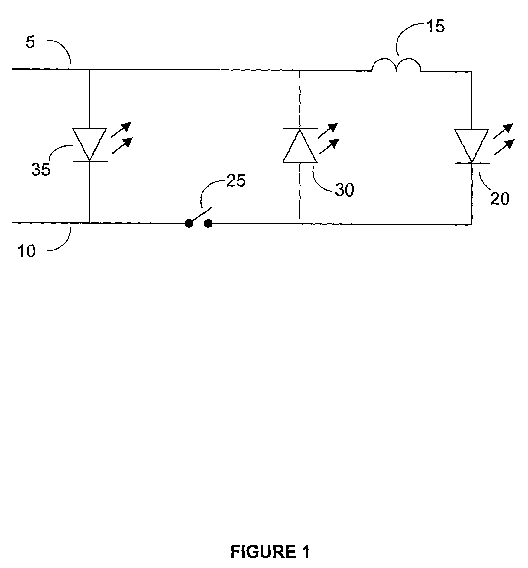
[0024]The invention is illustrated with the aid of various example and exemplary embodiments. The embodiments are categorized into two types, viz., non-isolated and isolated configurations. Non-isolated configurations do not provide isolation between the input and the output while isolated configurations isolate the input and output through transformers. Non-isolated configurations will be described first followed by isolated configuration.

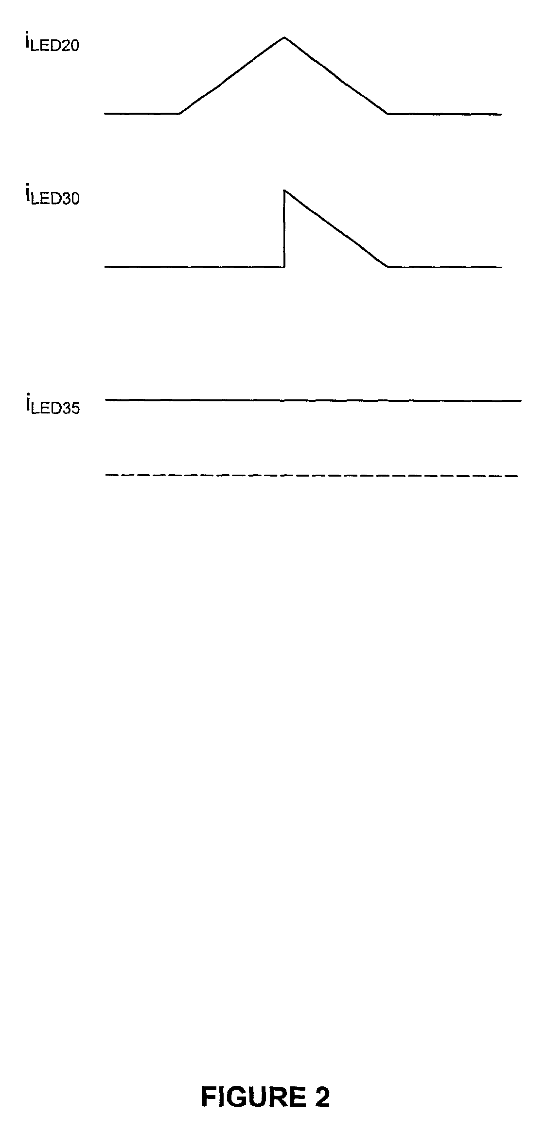
[0025]In each configuration a desired color is generated by combination of three primary colors, although such an arrangement is not required for practicing the invention. Accordingly, each configuration typically has three LEDs, or three sets of LEDs, producing primary colors blue, red and green. Combinations of different brightness of the colors produced by respective LEDs in a given configuration produce a variety of colors. Brightness of a LED is varied by varying the current through the LED. The described configurations enable modulation of c...


PUM


Abstract

An efficient power driver for color light emitting diodes (LED) is disclosed for driving multiple LEDs for producing different desired colors. Such LED combinations comprising LEDs with different primary colors are suitable for implementing pixels in displaying a digitized image. This disclosed invention provides switching power conversion embodiments such that a single apparatus drives different color LEDs. Furthermore, the disclosed invention provides configurations with and without input to output isolation while enabling control of the current through each LED, for instance by an inductor or operating condition.

Description

FIELD OF THE INVENTION[0001]This invention relates to the field of power converters, in particular to the field of power converters for Light Emitting Diodes (LED).BACKGROUND OF THE INVENTION[0002]Among many different types of electrical illuminating devices, Light Emitting Diode (LED) is becoming a popular light source increasing the utility of LEDs for many purposes including illumination. Light emitting diodes producing different colors, such as, red, blue and green LEDs are available. Combinations of these primary colors can produce almost any color enhancing LED use for many decorative lighting applications and illumination. A light emitting diode, being of small size, also has the potential to produce small size illumination apparatus, particularly with special power drivers to efficiently utilize them.[0003]LEDs are well suited for implementing a color pixel in a digital image display by combining several LEDs to generate a range of desired colors at the pixel. In order to dr...

Claims


Application Information

Patent Timeline
Patent Type & Authority Patents(United States)
IPC IPC(8): H01L27/14G05F1/00H05B44/00
CPCH05B33/0815H05B33/0818H05B33/0866H05B33/0824Y10S362/80H05B45/24H05B45/44H05B45/385H05B45/382
Inventor PONG, MAN HAYPOON, FRANKI NGAI KITLIU, JOE CHUI PONG
Owner HONG KONG THE UNIV OF
Why Eureka
Try Eureka