Assembly type nozzle diaphragm, and method of assembling the same

a technology of nozzle diaphragm and assembly type, which is applied in the direction of machines/engines, liquid fuel engines, forging/pressing/hammering apparatus, etc., can solve the problem of deterioration of performance, serious welding distortion, deviation of inside and outside diameters of steam paths from designed diameters, etc., and achieves the effect of reducing exchange operation and high turbine stage efficiency

Inactive Publication Date: 2007-02-20
KK TOSHIBA
View PDF25 Cites 25 Cited by
  • Summary
  • Abstract
  • Description
  • Claims
  • Application Information

AI Technical Summary

Benefits of technology

[0040]The assembled nozzle diaphragm according to the present invention having the characteristic features mentioned above can utilize the simple assembly structure in which the diaphragm outer ring insertion portion provided on one end of the nozzle blade is fitted to the diaphragm outer ring and in which the diaphragm inner ring insertion portion provided on the other end of the nozzle blade is fitted to the diaphragm inner ring. Therefore, at the time when the assembled nozzle diaphragm according to the present invention is applied to, for example, the steam turbine, the path width of the steam path can be kept exactly at the designed dimension and the turbine nozzle can be operated with far higher turbine stage efficiency.
[0041]In addition, with the nozzle diaphragm assembling method according to the present invention, the nozzle blade can be freely moved relative to the diaphragm inner and outer rings. Therefore, even if a damage such as a crack occurs to the nozzle blade during the operation of the steam turbine, it suffices to exchange only the nozzle blade to which the damage or the like occurs. Thus, differently from the conventional art, it is unnecessary to exchange the entire diaphragm and it is therefore possible to further reduce exchange operation.

Problems solved by technology

However, as international competition has been increasingly harsh, the market has demanded mare strictly improved performances and cost reduction for turbine nozzles.
(1) As to performance: deterioration of performance caused by manufacturing error resulting from welding distortion in the case of the weld-type turbine nozzle.
The most serious effect of the welding distortion is the deviation of inside and outside diameters of a steam path from designed diameters, respectively.
For this reason, even if a method for minimizing the welding distortion is discovered by trial and error, this method naturally has its limit, and as a result of the long-time use of the turbine nozzle, great positive or negative laps often appear again.
However, this method naturally has its limit, as well.
(2) As to cost: since there are many welding steps, it is difficult to realize cost reduction.
As a result, even if it is attempted to effectively reduce a material cost and a working cost, there is a limit to the cost reduction.
In addition, since it is difficult to mechanize and automate welding operation 100 percents, it is difficult to reduce the welding cost itself, accordingly.

Method used


Image

  • Assembly type nozzle diaphragm, and method of assembling the same
  • Assembly type nozzle diaphragm, and method of assembling the same
  • Assembly type nozzle diaphragm, and method of assembling the same

Examples


first embodiment

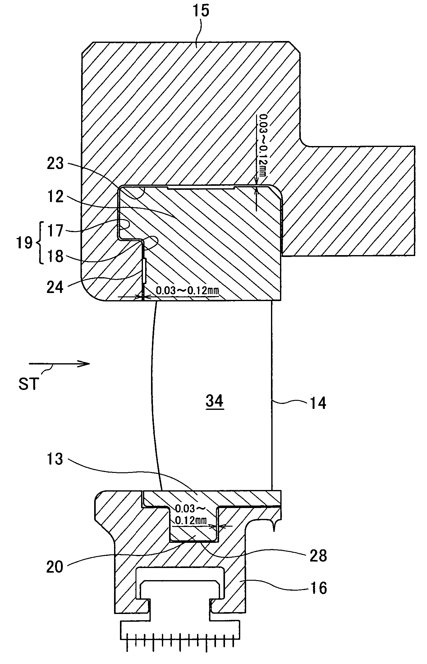
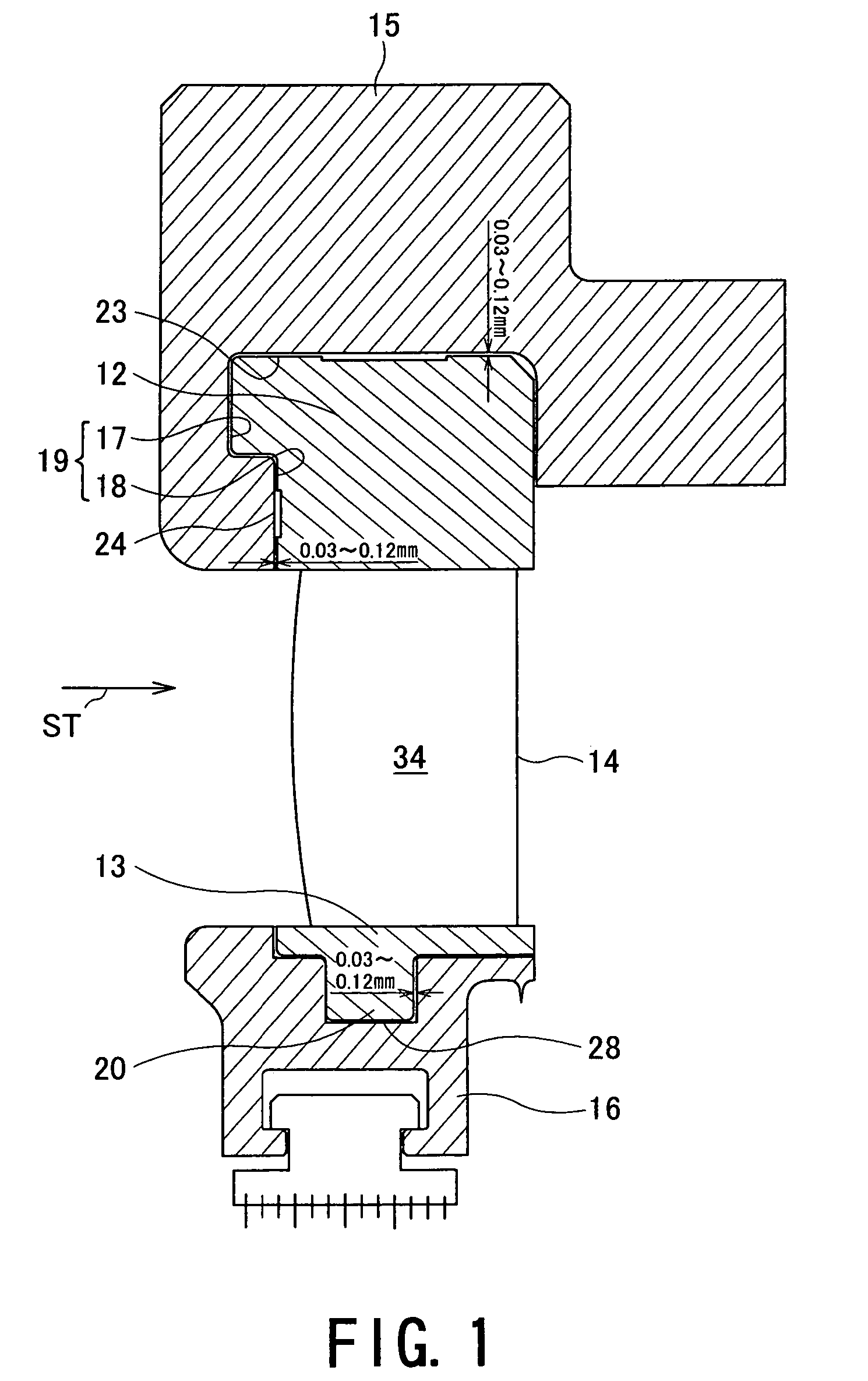
[0076]FIG. 1 is an elevational section which illustrates the assembled nozzle diaphragm according to the present invention.

[0077]The assembled nozzle diaphragm in this embodiment is constituted so that a nozzle blade (nozzle plate) 14 that includes a diaphragm outer ring insertion portion 12 and a diaphragm inner ring insertion portion 13 on both ends, respectively, a diaphragm outer ring 15 to which the diaphragm outer ring insertion portion 12 is fitted and which supports a head of the nozzle blade (nozzle plate) 14, and a diaphragm inner ring 16 to which the diaphragm inner ring insertion portion 13 is fitted and which supports a bottom of the nozzle blade (nozzle plate) 14.

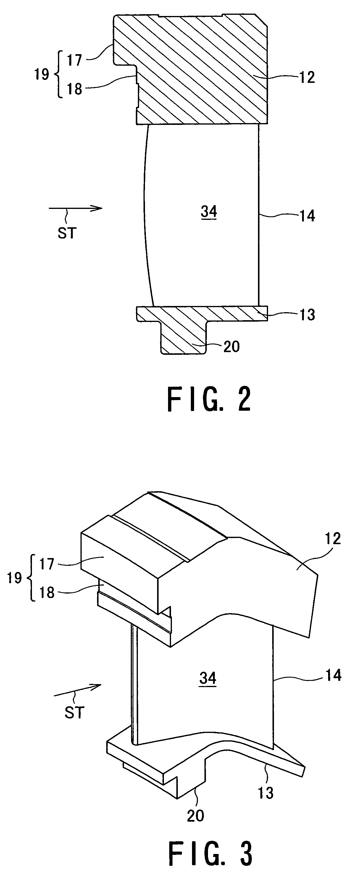
[0078]As shown in FIGS. 2 and 3, the diaphragm outer ring insertion portion 12 is formed together with the nozzle blade 14 by precision casting or by being integrally cut out from a nozzle blade element assembly through a machining process. An upstream side surface portion 19 of the nozzle outer ring insertion...

second embodiment

[0102]In the assembled nozzle diaphragm in this second embodiment, a T-shaped groove 35 is formed in the diaphragm outer ring 15, and the diaphragm outer ring insertion portion 12 fitted into this groove 35 is provided with protruded hook portions 38a and 38b formed on an upstream side surface 36 directed toward the flow of the steam ST and on a downstream side 37 directed toward the flow of the steam ST, respectively, stepped block portions 39a and 39b continuous to the respective hook portions, and base portions 40 continuous to the respective block portions.

[0103]These continuous hook portions 38a and 38b, block portions 39a and 39b, and base portions 40 are all formed together with the nozzle blade 14 by precision forging or by being integrally cut out from a nozzle blade element assembly by the machining work and formed so as to extend in the circumferential direction (moving blade rotating direction on the perpendicular plane relative to the steam flow). Since the other consti...

fourth embodiment

[0110]As is apparent from the above, in this fourth embodiment, at the time when the diaphragm outer ring insertion portion 12 is fitted and inserted into the diaphragm outer ring 15, the ring piece 44 is then interposed between the diaphragm outer ring insertion portion 12 and the diaphragm outer ring 15, and the coupled surface 46 between the diaphragm outer ring insertion portion 12 and the diaphragm outer ring 15 is sealed due to the pressing force of the bolt 45 engaged with the diaphragm outer ring 15. Therefore, the shakiness of the turbine nozzle can be surely prevented from causing and the turbine nozzle can be hence operated stably.

[0111]Further, in this embodiment, by utilizing the pressing force of the bolt 45, the coupled surface between the diaphragm outer ring insertion portion 12 and the diaphragm outer ring 15 is sealed. Therefore, it is not necessary to improve or maintain the accuracy of the fitting gap between the diaphragm outer ring insertion portion 12 and the...


PUM

PropertyMeasurementUnit
diameteraaaaaaaaaa
pressing forceaaaaaaaaaa
inner diameteraaaaaaaaaa

Abstract

A nozzle diaphragm assembly includes a diaphragm outer ring having a groove opened toward an inner diameter side to be continuous in an inner peripheral direction; a diaphragm inner ring having a groove opened toward an outer diameter side to be continuous in an outer peripheral direction; and a nozzle blade having a diaphragm outer ring insertion portion on one end and a diaphragm inner ring insertion portion on the other end, in which the groove opened toward the inner diameter side of the diaphragm outer ring and the diaphragm outer ring insertion portion are shaped to be fitted to each other, and in which the groove opened toward the outer diameter side of the diaphragm inner ring and the diaphragm inner ring insertion portion are shaped to be fitted to each other.

Description

TECHNICAL FIELD[0001]The present invention relates to an assembled nozzle diaphragm applied to a steam turbine and a method of assembling the nozzle diaphragm.BACKGROUND ART[0002]Generally, there has been often provided so-called an axial flow steam turbine, having large capacity, including a plurality of sages, arranged along steam flow direction, each comprising in combination a turbine nozzle (turbine stationary (stator) blade) and a turbine moving or movable (rotor) blade.[0003]The axial flow steam turbines will be roughly classified into reaction type and impulse type.[0004]The steam turbine of the impulse type causes thermal energy of a steam to perform more expansion work using each turbine nozzle, transforms the steam after the expansion work to a deflected flow using each turbine moving blade, and guides the resultant deflected flow to the next stage.[0005]In the turbine nozzle that converts most of the thermal energy of the steam to kinetic energy, a large pressure differe...

Claims


Application Information

Patent Timeline
Patent Type & Authority Patents(United States)
IPC IPC(8): F01D9/04F01D9/02F01D25/24
CPCF01D9/042F01D25/246Y10T29/49323F05D2240/10F05D2230/61F01D9/02
Inventor SASAKI, TAKASHINAKAMA, YUJIIMAI, KENICHI
Owner KK TOSHIBA
Why Eureka
Try Eureka