Method of dividing a non-metal substrate

a non-metal substrate and dividing line technology, applied in metal working equipment, manufacturing tools, welding/soldering/cutting articles, etc., can solve the problems of contaminating the semiconductor chip, reducing productivity, and limit the feed speed, so as to achieve smooth dividing along the dividing line

Active Publication Date: 2007-02-20
DISCO CORP
View PDF2 Cites 14 Cited by
  • Summary
  • Abstract
  • Description
  • Claims
  • Application Information

AI Technical Summary

Benefits of technology

[0005]It is an object of the present invention to provide a method of dividing a non-metal substrate along dividing lines by applying a laser beam with its converging point on the inside of the non-mal substrate to form a deteriorated layer along the dividing lines in the inside thereof, whereby the non-metal substrate can be divided along the dividing lines smoothly without generating chips.

Problems solved by technology

When the semiconductor chip is reduced in size, therefore, the proportion of the total of the streets occupying the top surface of the semiconductor wafer increases, thereby reducing productivity.
Cutting with the cutting blade involves problems that there is limitation to the feed speed and that the produced fine chips contaminate the semiconductor chip.
However, there is a case where a deteriorated layer cannot be exposed to one side that is the side to which a laser beam is applied even when the deteriorated layer is formed along the dividing lines in the inside of the non-metal substrate by applying a laser beam having an infrared range from one side of the non-metal substrate, with its converging point on the inside thereof.
Further, there is a problem that after a circuit such as LSI has been formed on the front surface of the silicon wafer having, for instance, a thickness of 500 μm and the rear surface of the silicon wafer has been ground to a thickness of 100 μm, even when a laser beam is applied from the rear surface of the silicon wafer with the converging point on the vicinity of the front surface to form a deteriorated layer so as to expose it to the front surface, the deteriorated layer is not exposed to the front surface uniformly and also to the rear surface uniformly.
Therefore, when external force is exerted on the non-metal substrate having a deteriorated layer formed therein along the dividing lines to divide it, the front surface side where the deteriorated layer is not formed cannot be divided at a right angle to the front surface, and chipping occurs with the result of a reduction in yield.

Method used


Image

  • Method of dividing a non-metal substrate
  • Method of dividing a non-metal substrate
  • Method of dividing a non-metal substrate

Examples


Embodiment Construction

[0024]The method of dividing a non-metal substrate according to the present invention will be described in more detail hereinbelow with reference to the accompanying drawings.

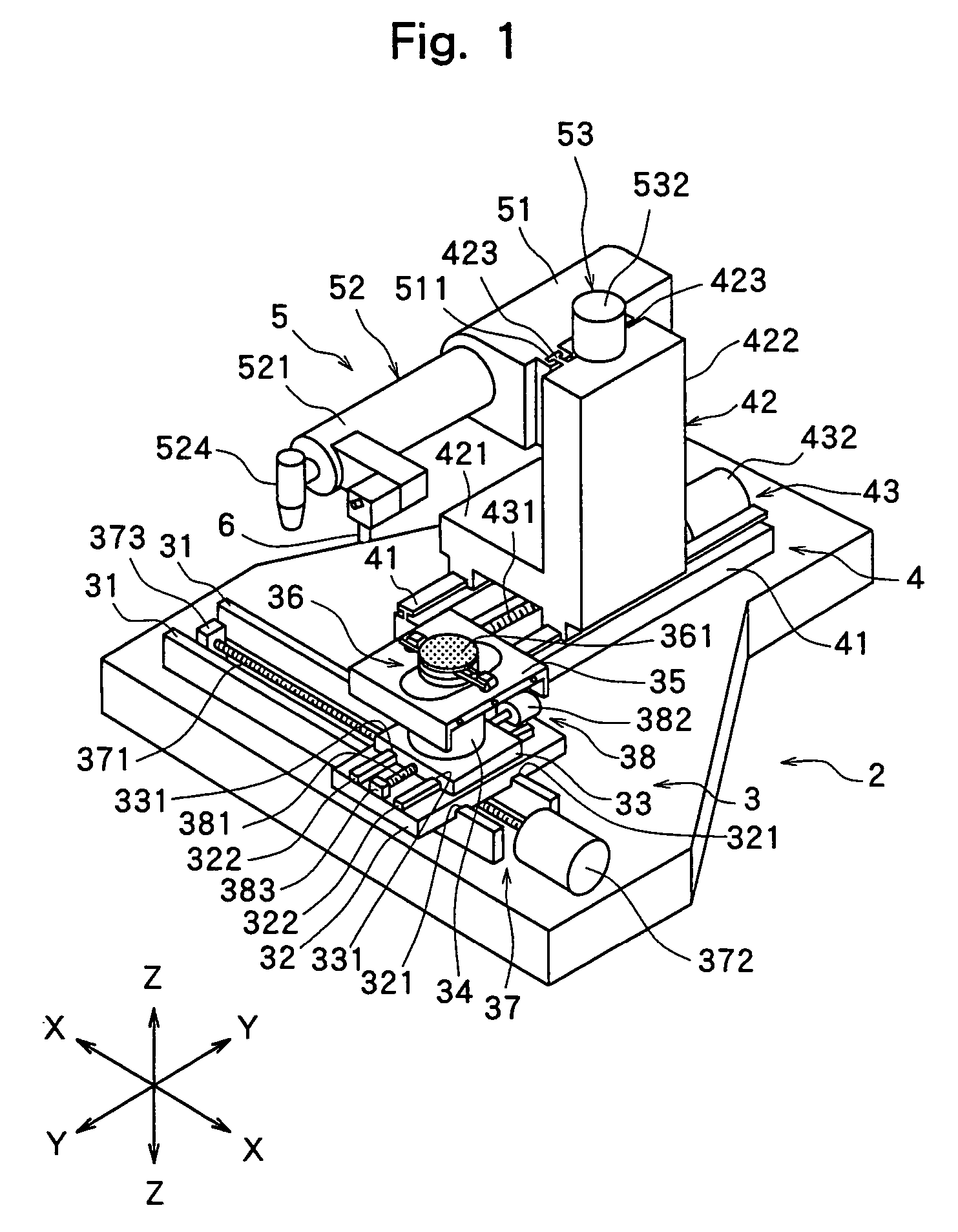
[0025]FIG. 1 is a perspective view of a laser beam machine for applying a laser beam to a non-metal substrate in the method of dividing a non-metal substrate such as a semiconductor wafer according to the present invention. The laser beam machine shown in FIG. 1 comprises a stationary base 2, a chuck table unit 3 for holding a workpiece, which is disposed on the stationary base 2 in such a manner that it can move in a direction indicated by an arrow X, a laser beam application unit support mechanism 4 disposed on the stationary base 2 in such a manner that it can move in a direction indicated by an arrow Y perpendicular to the direction indicated by the arrow X, and a laser beam application unit 5 disposed to the laser beam application unit support mechanism 4 in such a manner that it can move in a direction in...


PUM

PropertyMeasurementUnit
wavelengthaaaaaaaaaa
thicknessaaaaaaaaaa
thicknessaaaaaaaaaa

Abstract

A method of dividing a non-metal substrate having a first surface and a second surface formed parallel to the first surface, comprising:
    • a deteriorated layer forming step for forming a deteriorated layer in the inside of the non-metal substrate along dividing lines by applying a laser beam capable of passing through the non-metal substrate from the first surface side with its converging point on the inside thereof; and
    • a deteriorated layer exposing step for exposing the deteriorated layer to the first surface by grinding the first surface side of the non-metal substrate having the deteriorated layer formed therein.

Description

FIELD OF THE INVENTION[0001]The present invention relates to a method of dividing a non-metal substrate such as a semiconductor wafer along predetermined dividing lines.FIELD OF THE INVENTION[0002]As is known to people of ordinary skill in the art, in the production of a semiconductor device, a plurality of areas are sectioned by streets (dividing lines) formed on the front surface of a substantially disk-like semiconductor wafer in a lattice form, and a circuit such as IC or LSI is formed in each of the sectioned areas. The semiconductor wafer is cut along the streets to separate the circuit-formed areas from one another, thereby manufacturing individual semiconductor chips. Cutting along the streets of the semiconductor wafer is generally carried out by a cutting machine called “dicer”. This cutting machine comprises a chuck table for holding a semiconductor wafer as a workpiece, a cutting means for cutting the semiconductor wafer held on the chuck table, and a moving means for mo...

Claims


Application Information

Patent Timeline
Patent Type & Authority Patents(United States)
IPC IPC(8): H01L21/00B23K26/38B23K26/40B23K101/40H01L21/301H01L21/304H01L21/78
CPCB23K26/0057H01L21/67092H01L21/78B23K26/0063B23K26/4075B23K26/0853B23K2201/40B23K26/40B23K26/53B23K26/57B23K2101/40B23K2103/50
Inventor NAGAI, YUSUKE
Owner DISCO CORP
Why Eureka
Try Eureka