Eureka AIR delivers breakthrough ideas for toughest innovation challenges, trusted by R&D personnel around the world.

Dye sensitized solar cells having foil electrodes

Active Publication Date: 2007-02-20
GENERAL ELECTRIC CO
View PDF10 Cites 8 Cited by
  • Summary
  • Abstract
  • Description
  • Claims
  • Application Information

AI Technical Summary

Problems solved by technology

During the random walk of the electron to the electrode, the electron may travel a significant distance, and the electron may be lost by combining with a component of the electrolyte solution, also known as “recombination.” Under irradiation by sunlight the density of electrons in the semiconductor may be very high such that such losses significantly reduce the maximum voltage and therefore the efficiency achievable by the solar cells.
Disadvantageously, reduction in the thickness of the semiconductor film may reduce the light absorption in the dye, thereby reducing the efficiency of the solar cell.
However, as previously described, reducing the thickness of the semiconductor film may reduce the light absorption potential of the dye.
Although longer light paths may be desirable to facilitate greater light absorption, the losses due to the increased recombination of the electrons into the semiconductor layer, as well as limits to current caused by slow ion diffusion through the electrolyte in the semiconductor pores, make the increased thickness in the semiconductor film disadvantageous since it may produce a less efficient solar cell.

Method used


Image

  • Dye sensitized solar cells having foil electrodes
  • Dye sensitized solar cells having foil electrodes
  • Dye sensitized solar cells having foil electrodes

Examples


Embodiment Construction

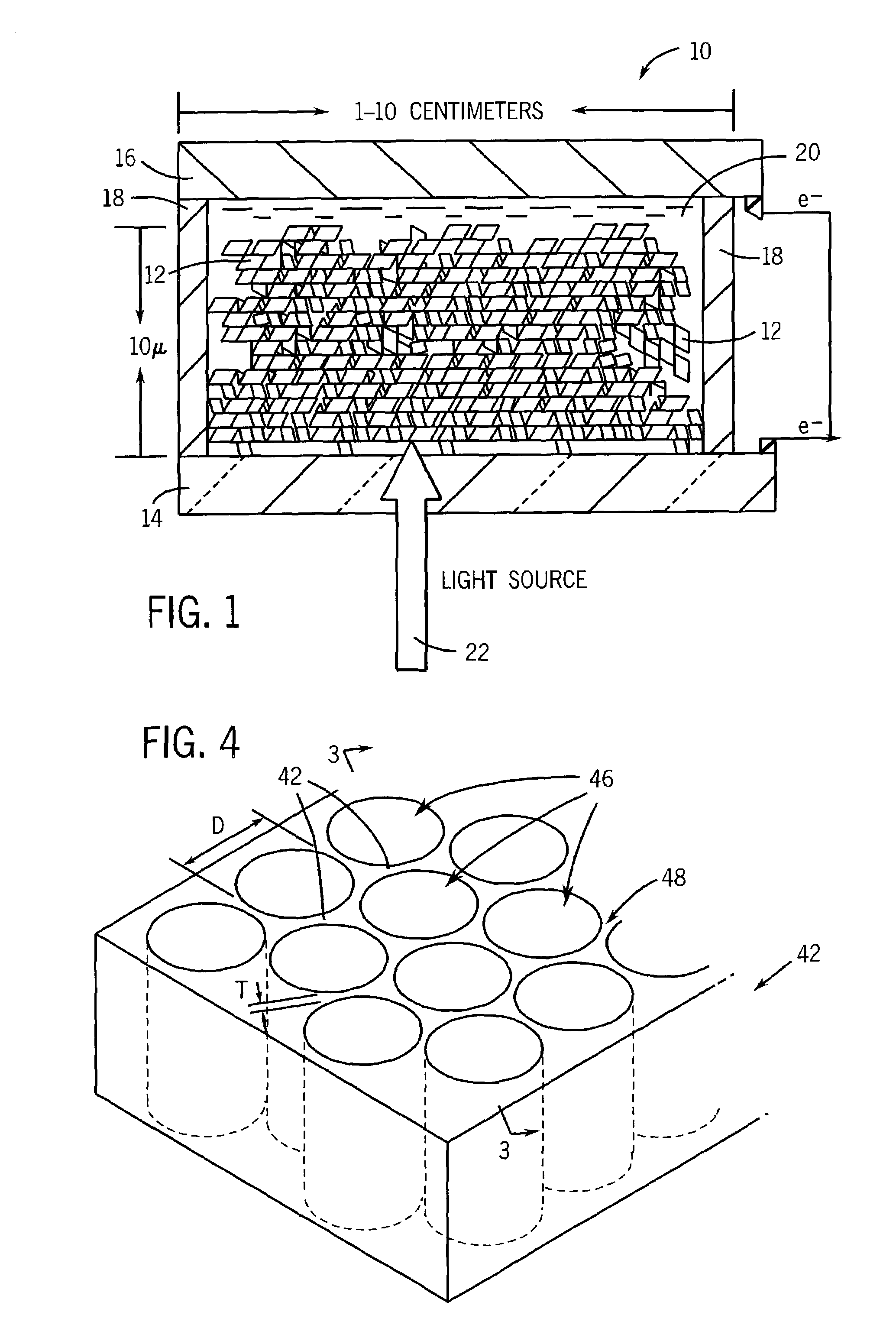
[0022]FIG. 1 illustrates an exemplary embodiment of a dye-sensitized solar cell 10. As can be appreciated, the solar cell 10 may be constructed by implementing planar layered structures. The solar cell 10 may be fabricated by implementing any one of a number of techniques and using a variety of materials, as can be appreciated by those skilled in the art. In one embodiment, a layer of semiconductor material, such as a layer of nanocrystalline titanium dioxide (TiO2) 12 may be disposed on a transparent substrate 14, such as a glass substrate. The substrate 14 is coated with a conductive layer such as a transparent conducting oxide (TCO) layer. The TCO coated transparent substrate 14 forms the front electrode of the solar cell 10. As can be appreciated, the substrate 14 may comprise other transparent materials such as plastic. The TiO2 layer 12 may be disposed at a thickness in the range of 5–20 microns, for example. The TiO2 layer 12 is generally disposed at a thickness of at least 1...


PUM


Abstract

A solar cell having foil electrodes. Specifically, a metal foil is implemented to form electrodes providing a reduced electron path from a dye-sensitized semiconductor material to the electrodes. In one embodiment, nanowires extending from the substrate on which the solar cell is formed are provided. In another embodiment, cavities are formed in a sheet of conductive foil by oxidation, thereby forming a semiconductive material. The semiconductive material is sensitized with a dye and an electrolyte solution is disposed in the cavities, thereby forming an array of dye-sensitized solar cells.

Description

CROSS-REFERENCE TO RELATED APPLICATIONS[0001]The following commonly owned applications and patents are hereby incorporated by reference for all purposes:[0002]U.S. patent application Ser. No. 10 / 316,317, filed concurrently herewith, entitled “Structured Dye Sensitized Solar Cell” by James L. Spivack and Harish R. Acharya, now U.S. Pat. No. 7,019,209;[0003]U.S. patent application Ser. No. 10 / 316,519, filed concurrently herewith, entitled “Structured Micro-Channel Semiconductor Electrode For Photovoltaic Cells” James L. Spivack and Donald F. Foust, now U.S. Pat. No. 7,078,613; and[0004]U.S. patent application Ser. No. 10 / 316,498, filed concurrently herewith, entitled “Dye Sensitized Solar Cell Having Finger Electrodes” by James L. Spivack, Harish R. Acharya, and Donald F. Foust.BACKGROUND OF THE INVENTION[0005]Generally speaking, photovoltaic systems are implemented to convert light energy into electricity for a variety of applications. Power production by photovoltaic systems may off...

Claims


Application Information

Patent Timeline
IPC IPC(8): H01L31/00H01G9/20H01L21/316
CPCH01G9/2031Y02E10/542H01L21/31683H01G9/2059H01L21/02244
Inventor SPIVACK, JAMES L.GUI, JOHN YUPENGCORDERMAN, REED ROEDER
Owner GENERAL ELECTRIC CO
Why Eureka
Eureka Blog
Learn More