Load control circuit
a load control and circuit technology, applied in pulse generators, instruments, pulse techniques, etc., can solve the problems of large variable resistors and large vehicle light adjustment systems, and achieve the effect of reducing the size of the brightness adjustment systems
- Summary
- Abstract
- Description
- Claims
- Application Information
AI Technical Summary
Benefits of technology
Problems solved by technology
Method used
Image

Examples
first embodiment
[First Embodiment]
[0035]A load control circuit according to a first embodiment of the present invention will now be discussed with reference to FIGS. 2 to 5.
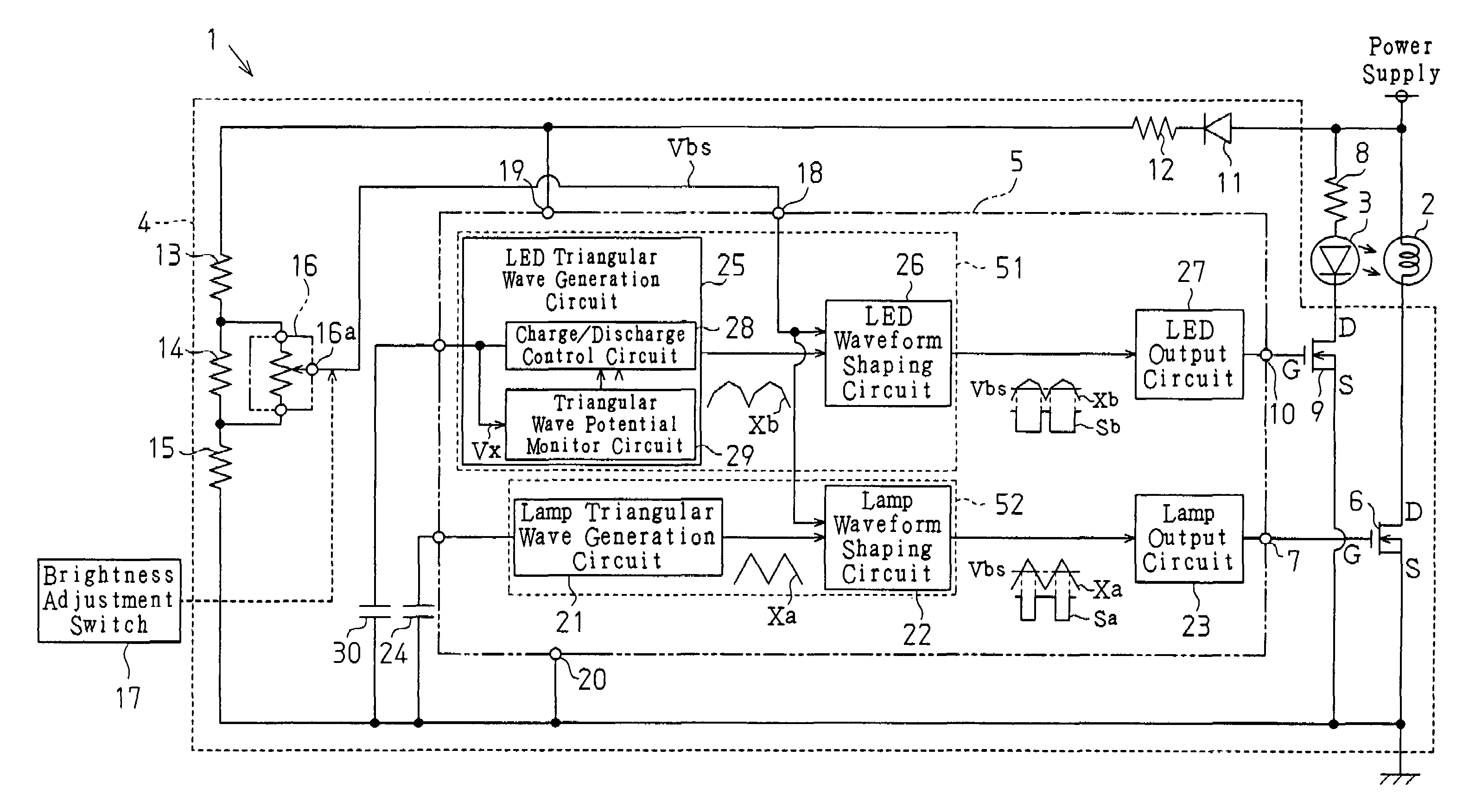
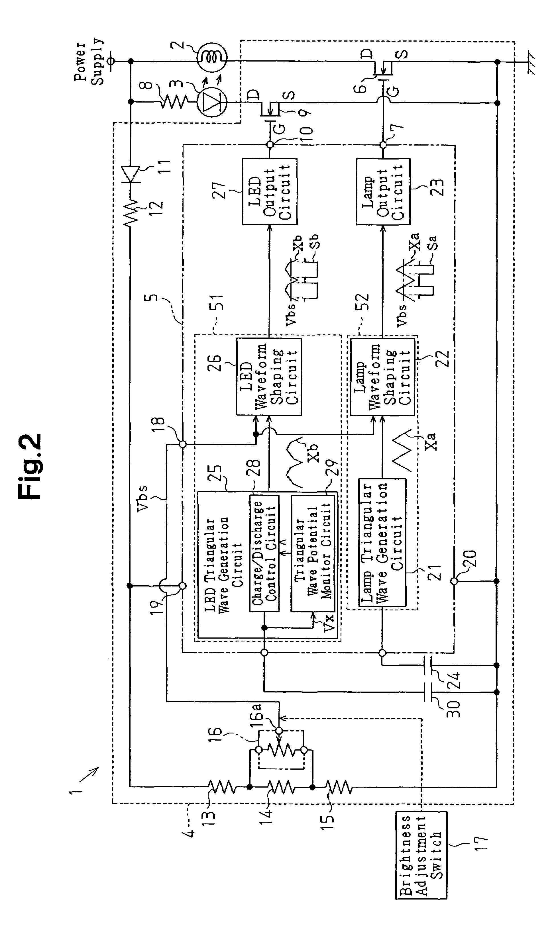
[0036]FIG. 2 is a block diagram showing the electric configuration of a vehicle light adjustment system 1. The vehicle light adjustment system 1 includes a plurality of LEDs 3 (first load), a plurality of lamps (second load) 2, a rheostat (light adjusting device) 4, and a brightness adjustment switch 17. For the sake of simplicity, only one lamp 2 and one LED 3 are shown in FIG. 2. Each lamp 2 illuminates a meter, such as a speedometer or a tachometer. Each LED 3 illuminates a switch, such as an air conditioner switch and a car stereo switch. The rheostat 4 controls the illumination of the lamp 2 and the LED 3. The rheostat 4 includes a duty ratio control circuit 5 (load control circuit) for generating a duty signal Sa, which drives the lamp 2, and a duty signal Sb, which drives the LED 3. The duty ratio control circuit 5 includ...
second embodiment
[Second Embodiment]
[0060]A second embodiment of the present invention will now be discussed with reference to FIGS. 6 to 8. The second embodiment differs from the first embodiment only in how the LED triangular wave signal is output.
[0061]FIG. 7 is a block diagram showing the electric configuration of the vehicle light adjustment system 1. The duty ratio control circuit 5 includes a first LED triangular wave generation circuit 35, a second LED triangular wave generation circuit 36, and a switching circuit 37. A capacitor 38 is connected between the first LED triangular wave generation circuit 35 and the ground. A capacitor 39 is connected between the second LED triangular wave generation circuit 36 and the ground. The output of the first LED triangular wave generation circuit 35 and the output of the second LED triangular wave generation circuit 36 are connected to the switching circuit 37. The switching circuit 37 is connected to the LED waveform shaping circuit 26. Further, the sw...
third embodiment
[Third Embodiment]
[0076]A third embodiment of the present invention will now be discussed with reference to FIGS. 9 and 10. The third embodiment differs from the first and second embodiments only in how the LED triangular wave signal is output.
[0077]FIG. 9 is a block diagram showing the electric configuration of the vehicle light adjustment system 1. The duty ratio control circuit 5 includes a single triangular wave generation circuit 40 and a reference potential input / output circuit 41. The triangular wave generation circuit 40 is connected to the lamp waveform shaping circuit 22 and the LED waveform shaping circuit 26. Further, the triangular wave generation circuit 40 is shared by the lamp waveform shaping circuit 22 and the LED waveform shaping circuit 26. The triangular wave generation circuit 40, the reference potential input / output circuit 41, and the LED waveform shaping circuit 26 configure a first duty signal generation circuit 54. The triangular wave generation circuit 40...
PUM
 Abstract
Description
Claims
Application Information
 - R&D
- Intellectual Property
- Life Sciences
- Materials
- Tech Scout
- Unparalleled Data Quality
- Higher Quality Content
- 60% Fewer Hallucinations
Browse by: Latest US Patents, China's latest patents, Technical Efficacy Thesaurus, Application Domain, Technology Topic, Popular Technical Reports.
© 2025 PatSnap. All rights reserved.Legal|Privacy policy|Modern Slavery Act Transparency Statement|Sitemap|About US| Contact US: help@patsnap.com