
Devices including a thermally conductive member which guides heat produced by an image capturing unit to a display chassis

Inactive Publication Date: 2007-02-20
OLYMPUS CORP
View PDF7 Cites 42 Cited by
  • Summary
  • Abstract
  • Description
  • Claims
  • Application Information

AI Technical Summary

Benefits of technology

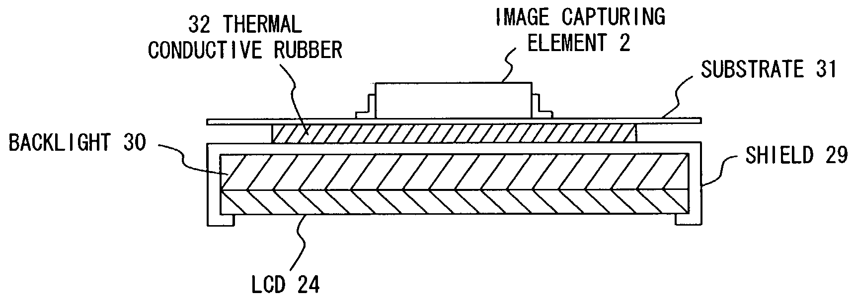
[0011]With this configuration, the heat produced by the solid-state image capturing element, or heat produced by an element, which exerts a thermal influence on the solid-state image capturing element, is transferred to the display chassis and radiated, so that the solid-state image capturing element is cooled. Accordingly, a captured image of good image quality can be obtained without arranging a radiator dedicated to the solid-state image capturing element.
[0034]With the above described configuration, the heat produced by the solid-state image capturing element is transferred to the static electricity shielding unit, which is intended to improve the tolerance of the static electricity applied to the image display unit, and the heat is radiated from the static electricity shielding unit, thereby eliminating the need for a radiator dedicated to the solid-state image capturing element.

Problems solved by technology

Since a solid-state image capturing element is normally configured by using a semiconductor, noise caused by heat occurs within the element.
This thermal noise (also called dark noise, etc.) monotonously increases with a rise in the temperature of the element.
However, the solid-state image capturing element is an active element, and produces heat at the time of operations.
However, the demand for further reducing digital cameras, which have become widespread in these days, in size, thickness, and weight is high.
This poses a problem that a dedicated space where a radiator for an image capturing element is arranged cannot be secured within the chassis of a digital camera.

Method used


Image

  • Devices including a thermally conductive member which guides heat produced by an image capturing unit to a display chassis
  • Devices including a thermally conductive member which guides heat produced by an image capturing unit to a display chassis
  • Devices including a thermally conductive member which guides heat produced by an image capturing unit to a display chassis

Examples


Embodiment Construction

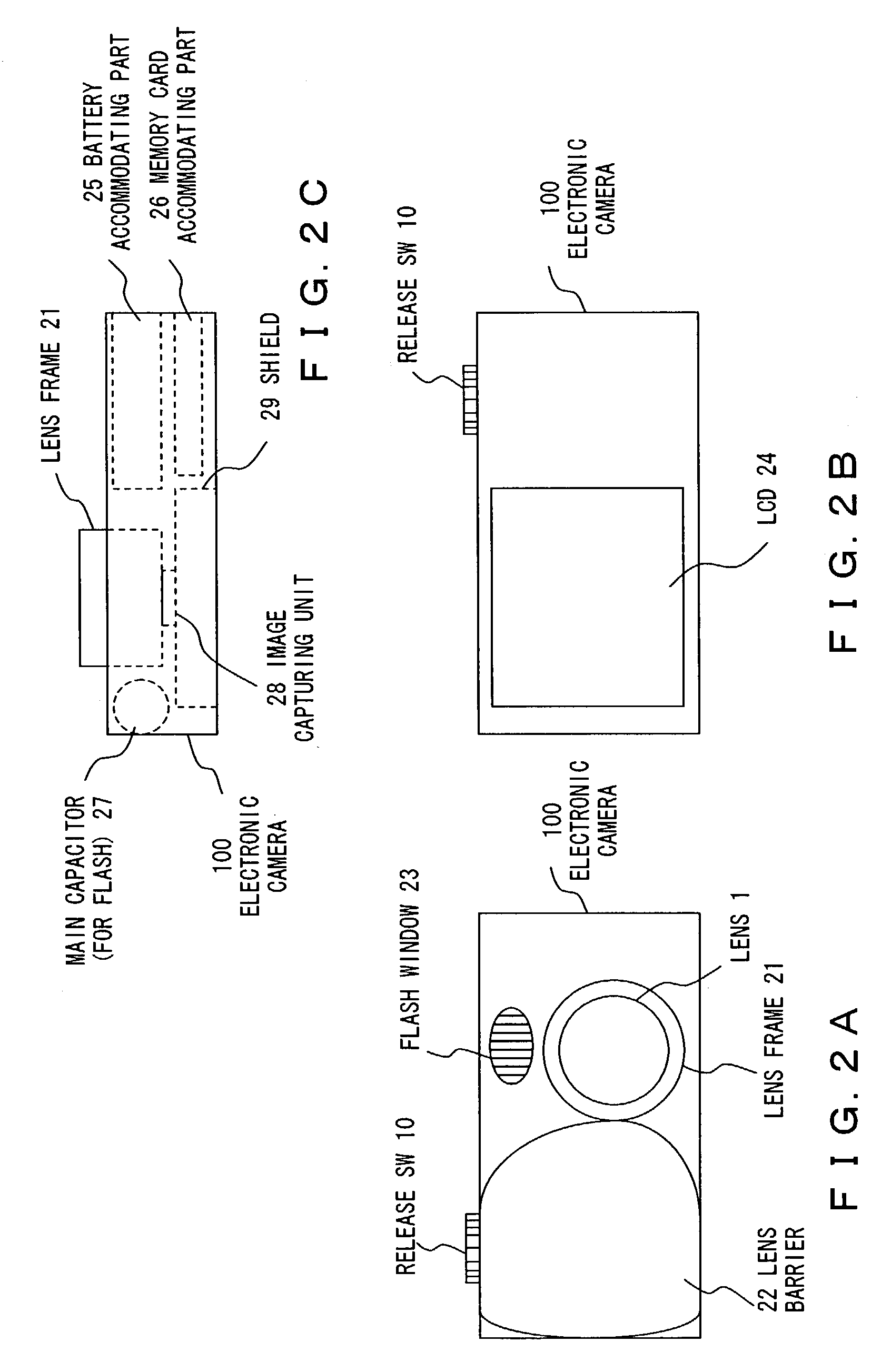
[0046]Hereinafter, preferred embodiments according to the present invention are described with reference to the drawings.

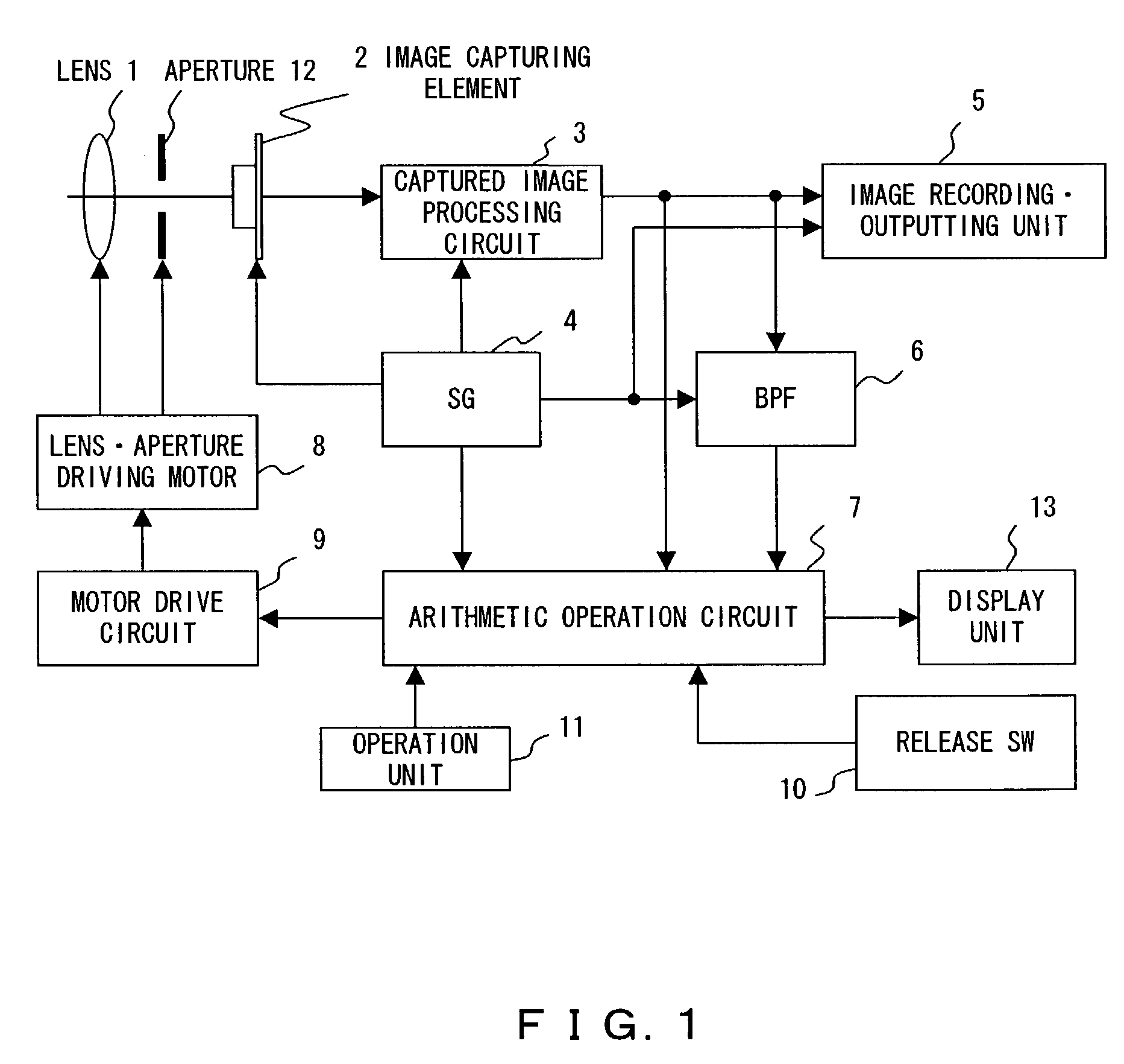
[0047]FIG. 1 shows the electric configuration of an electronic camera, which is an image capturing device implementing the present invention.

[0048]The electronic camera (hereinafter referred to as “this device”) shown in FIG. 1 is configured to comprise: a lens 1 which forms a subject image on a light-receptive surface of an image capturing element 2; an aperture 12 which restricts the amount of light incident to this device via the lens 1 depending on need; a lens / aperture driving motor 8 used to move the lens 1 for focusing, or to adjust the aperture 12 for suitable exposure; a motor drive circuit 9 which controls the lens / aperture driving motor 8; an image capturing element 2 which converts the subject image formed by the lens 1 into an electric signal; a captured image processing circuit 3 which performs processes such as amplification, sample and hold, analog...


PUM


Abstract

An LCD having a backlight is inserted in a shield for protecting various types of electronic components used in an electronic camera by shielding static electricity applied to the LCD, and the LCD is held by the shield. In this structure, thermal conductive rubber is interposed between a substrate on which an image capturing element is arranged, and the shield, so that the image capturing unit composed of the image capturing element and the substrate, and the shield are thermally bonded.

Description

BACKGROUND OF THE INVENTION[0001]1. Field of the Invention[0002]The present invention relates to a technique for use in an image capturing device of an electronic camera, etc., and more particularly, to a technique for improving the image quality of a captured image.[0003]2. Description of the Related Art[0004]In recent years, an image capturing device, which uses a solid-state image capturing element such as a CCD (Charge Coupled Device), etc. as an image capturing element that converts a subject image into an electric signal, has become widespread.[0005]Since a solid-state image capturing element is normally configured by using a semiconductor, noise caused by heat occurs within the element. This thermal noise (also called dark noise, etc.) monotonously increases with a rise in the temperature of the element. Therefore, if an image is captured by dropping the temperature of an image capturing element as low as possible, thermal noise less occurs, and the image quality of the captu...

Claims


Application Information

Patent Timeline
IPC IPC(8): H04N5/225G03B7/22G03B17/02G03B17/18H01L23/36
CPCH04N5/2253H01L2924/0002H01L2924/00H04N23/54
Inventor KOBAYASHI, KAZUYA
Owner OLYMPUS CORP
Learn More