
Implantable heart stimulating device, system and method

a heart stimulation and implantable technology, applied in electrotherapy, physical therapy, artificial respiration, etc., can solve the problems of ventricular arrhythmia, the best time delay for achieving simultaneous contraction of the ventricles may not be the same as the optimal time delay, etc., to reduce the risk of ventricular arrhythmia, reduce the risk of arrhythmia, and reduce the risk of such an arrhythmia

Inactive Publication Date: 2007-02-20
ST JUDE MEDICAL
View PDF12 Cites 1 Cited by
  • Summary
  • Abstract
  • Description
  • Claims
  • Application Information

AI Technical Summary

Benefits of technology

[0013]An object of the present invention is to reduce the risk for arrhythmia in a bi-ventricular heart-stimulating device of this kind. A more particular object is to reduce the risk for arrhythmia that may be caused by PVCs in such a heart-stimulating device. A further object is to provide such a heart-stimulating device, in which, in addition to reducing the risk for such an arrhythmia, also the hemodynamic performance of the heart is favored in case of PVCs.
[0015]The device is thus arranged to operate with a first time delay VV as well as with at least one additional time delay, VVPVC1 and / or VVPVC2. The first time delay can be set to optimize the synchronization of the contraction of the ventricles. With the first time delay VV, the hemodynamic performance of the heart may thus be optimized. The second and / or third time delays can be set to a different value than VV. The second and / or third time delays may be set to reduce the risk for arrhythmia in certain situations. In particular, as has been described above, a PVC may cause a ventricular arrhythmia. In order to reduce the risk for such an arrhythmia, it is important to try to avoid a situation where the ventricles are in different states concerning depolarization. By setting an appropriate VVPVC1 and / or VVPVC2, the depolarization of the two ventricles can be optimized such that they occur synchronously. Thereby, the likelihood of arrhythmia is reduced. It should be pointed out that the best time delay for achieving simultaneous contraction of the ventricles may not be the same as the optimal time delay in order to synchronize the depolarization of the ventricles. Therefore, according to the present invention, since the second and / or third time delays VVPVC1, VVPVC2 can be set to be different from the first time delay VV, the operation of the device is optimized in order to reduce the risk for arrhythmia at the same time as the device, in its normal operation, is optimized for synchronizing the contraction of the ventricles.
[0020]Preferably, each of the first, second and third time delays is shorter than 80 ms, most preferably shorter than 40 ms. Such lengths of the mentioned time delays are normally beneficial in order to synchronize the contraction of the ventricles or to reduce the risk for arrhythmia in the event of a PVC.
[0022]In a preferred embodiment, the control circuit operates to determine whether a signal sensed by the first or second sensing circuit belongs to the aforementioned category, and, if this is the case, to deliver a pacing pulse, in accordance with the predefined pacing rule, with the first pacing circuit if the signal in the category was sensed by the second sensing circuit and with the second pacing circuit if the signal in the category was sensed by the first sensing circuit. When a signal typical of a PVC is detected by, for example, the first sensing circuit, a pacing pulse is delivered with the second pacing means. In this manner, the depolarization of the ventricles can be synchronized. At the same time also the hemodynamic performance is improved, since also the contraction of the ventricles, in case of a PVC, is likely to be more synchronized than if no such pacing pulse were delivered with the second pacing circuit.
[0030]The heart stimulating system preferably is used to react to a premature ventricular contraction such that the risk for arrhythmia is reduced. The system can be used to treat a human or animal suffering from congestive heart failure, for example when the human or animal suffers from a bundle branch block.

Problems solved by technology

In particular, as has been described above, a PVC may cause a ventricular arrhythmia.
It should be pointed out that the best time delay for achieving simultaneous contraction of the ventricles may not be the same as the optimal time delay in order to synchronize the depolarization of the ventricles.

Method used


Image

  • Implantable heart stimulating device, system and method
  • Implantable heart stimulating device, system and method
  • Implantable heart stimulating device, system and method

Examples


Embodiment Construction

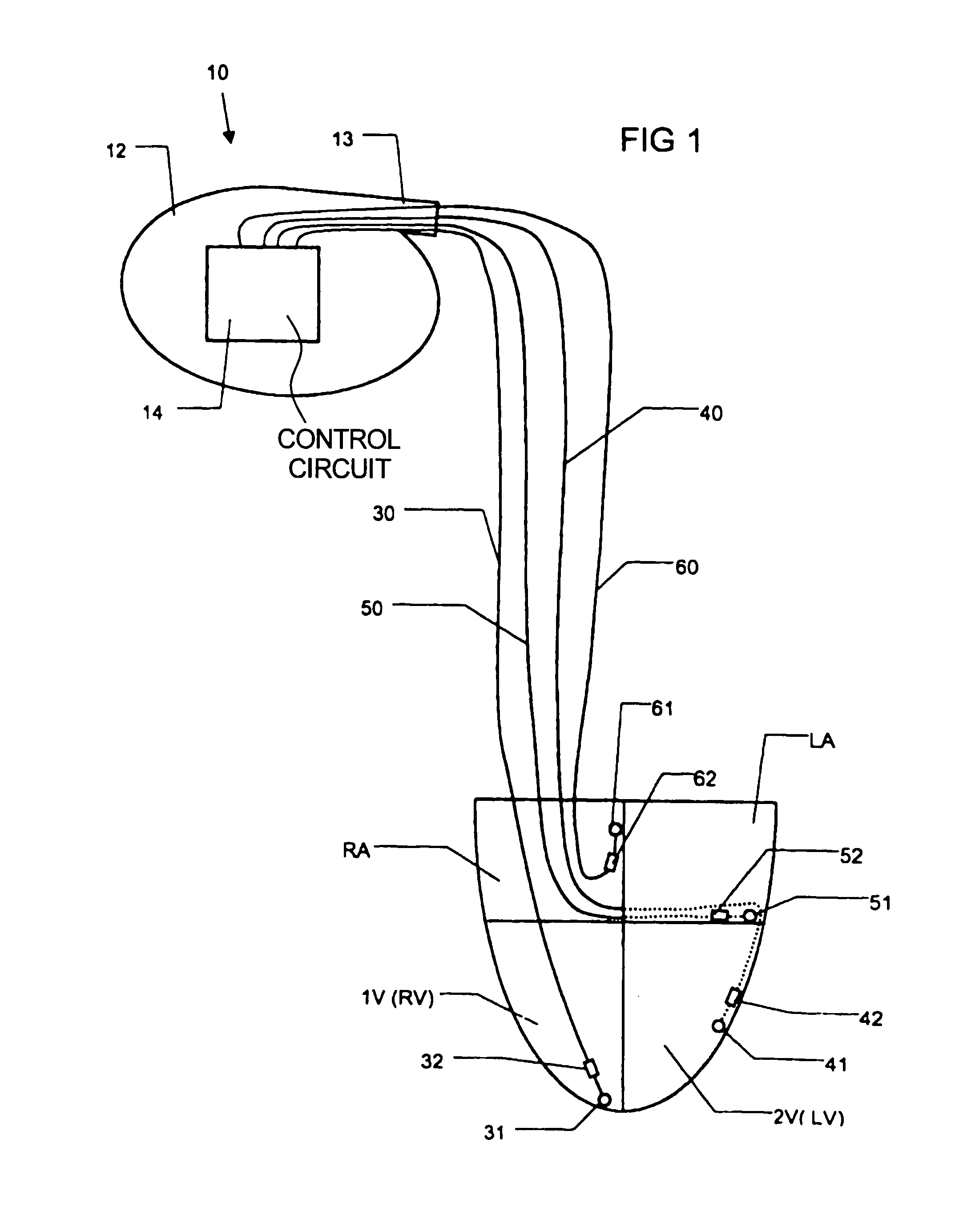
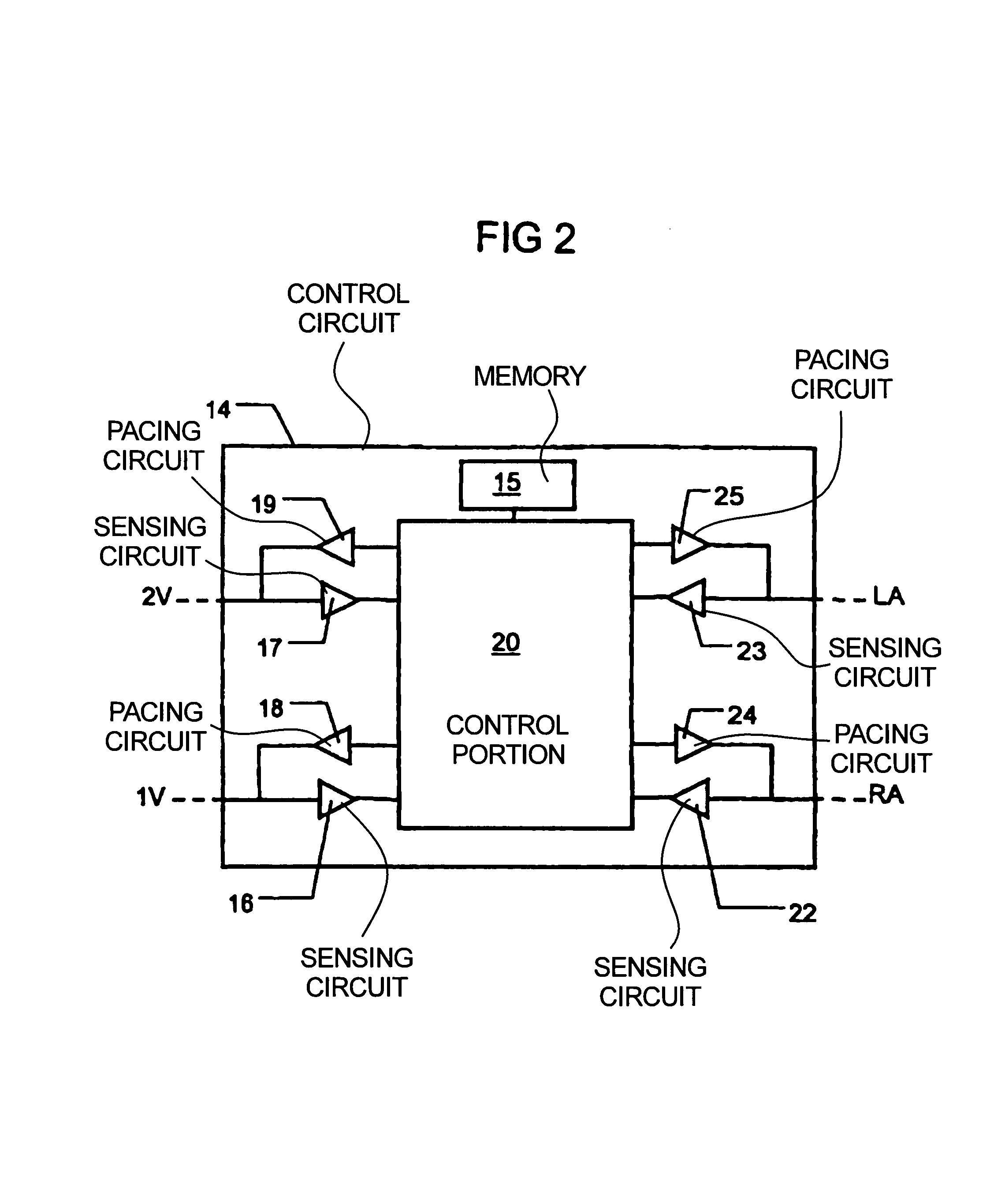
[0036]FIG. 1 schematically shows an implantable heart-stimulating device 10 according to the invention. The device 10 has a housing 12. The device 10 contains a control circuit 14 (that will be described more in connection with FIG. 2). The device 10 has a connector portion 13. The device 10 is in the illustrated embodiment connected to different leads 30, 40, 50, 60.

[0037]FIG. 1 also schematically shows a heart having a right atrium RA, a left atrium LA, a right ventricle RV and a left ventricle LV.

[0038]A first lead 30 includes electrode members 31, 32 positioned in the right ventricle RV of the heart. The electrode member 31 may be called a tip electrode and the electrode member 32 can be called a ring electrode. In this example, the first lead 30 thus includes a bipolar electrode. However, it is within the scope of the invention that the device 10 instead is connected to unipolar electrodes as is known to those skilled in the art. The electrode formed by the electrode members 31...


PUM


Abstract

An implantable bi-ventricular heart stimulating device and system operate, within a time cycle, to deliver pacing pulses with both a first and a second pacing circuit with a first time delay between these pacing pulses. The device employs a criterion with which a signal typical for a premature ventricular contraction is detected. The device also operates with a second time delay and / or with a third time delay, and, if a predefined pacing rule is fulfilled, to deliver a pacing pulse with the second time delay or said third time delay. The risk for arrhythmia in connection with a PVC is reduced.

Description

BACKGROUND OF THE INVENTION[0001]1. Field of the Invention[0002]The present invention relates to an implantable heart-stimulating device with which it is possible to stimulate both ventricles of a heart, i.e. a bi-ventricular pacer.[0003]The invention also relates to a system including such a device and to the use of the system.[0004]2. Description of the Prior Art[0005]Several different implantable devices for stimulating a heart are known. The devices are normally able to sense the electrical activity of the heart. Some implantable devices are able to deliver stimulation pulses to both the left and right ventricles of the heart, and sometimes also to the left and right atria.[0006]Devices that are able to deliver stimulation pulses to both the left and right ventricles are also called bi-ventricular pacers. Such de-vices can be used to treat patients who suffer from different severe cardiac problems, e.g. patients suffering from congestive heart failure (CHF). CHF is defined gener...

Claims


Application Information

Patent Timeline
Patent Type & Authority Patents(United States)
IPC IPC(8): A61N1/36A61N1/362A61N1/368
CPCA61N1/3622A61N1/3627A61N1/3684A61N1/36843
Inventor BJORLING, ANDERSHOLMSTROM, NILSJARVERUD, KARIN
Owner ST JUDE MEDICAL
Learn More