Vibration control device

a technology of vibration control and control device, which is applied in adaptive control, shock absorbers, instruments, etc., can solve the problems of increasing the overall cost of the system, affecting the overall response of the system, and the vibration of the robot arm b>1/b> tends to be easy to occur, so as to achieve the effect of suppressing the vibration of the movable part and stable respons

Inactive Publication Date: 2007-02-20
FANUC LTD
View PDF25 Cites 11 Cited by
  • Summary
  • Abstract
  • Description
  • Claims
  • Application Information

AI Technical Summary

Benefits of technology

[0020]It is an object of the present invention to provide a control device for controlling the motion of a movable part in a machine, wherein it is possible to effectively suppress the vibration of the movable part by performing a state-feedback type control which does not require a vibration detector to be provided on the movable part, and wherein it is possible to ensure a stable response by actively causing the state variable of a controlled system to follow a command or desired value.

Problems solved by technology

Accordingly, in a case where the movable part is moved at high speed and stopped at a target position, the movable part tends to vibration easily.
However, as described, there arises the problem that the robot arm 1 tends to vibrate because of the interposition of a transmission mechanism such as the low-rigidity reduction mechanism 2.
Thus, in a case where a detector is mounted on the movable part of the machine, it is necessary to provide a number of supplementary units, such as a cable and a signal receiving circuit, in order to acquire feedback signals from the detectors, and this may lead to an increase in the overall cost of the system.
There is also concern that the maintenance cost of each individual unit may increase.
Furthermore, the reliability of the system may degrade due to the increased number of parts.
However, depending on the configuration of the machine to which the method is applied, there may be a case where the controlled system is unstable and a sufficient feedback gain cannot be obtained.
Further, the feedback gain needs to be determined in correspondence to the characteristics of the machine, but generally it is difficult to obtain an optimum value for the feedback gain.

Method used


Image

  • Vibration control device
  • Vibration control device
  • Vibration control device

Examples


Embodiment Construction

[0054]The embodiments of the present invention are described below, in detail, with reference to the accompanying drawings. Throughout the drawings, the same or similar components are denoted by common reference numerals.

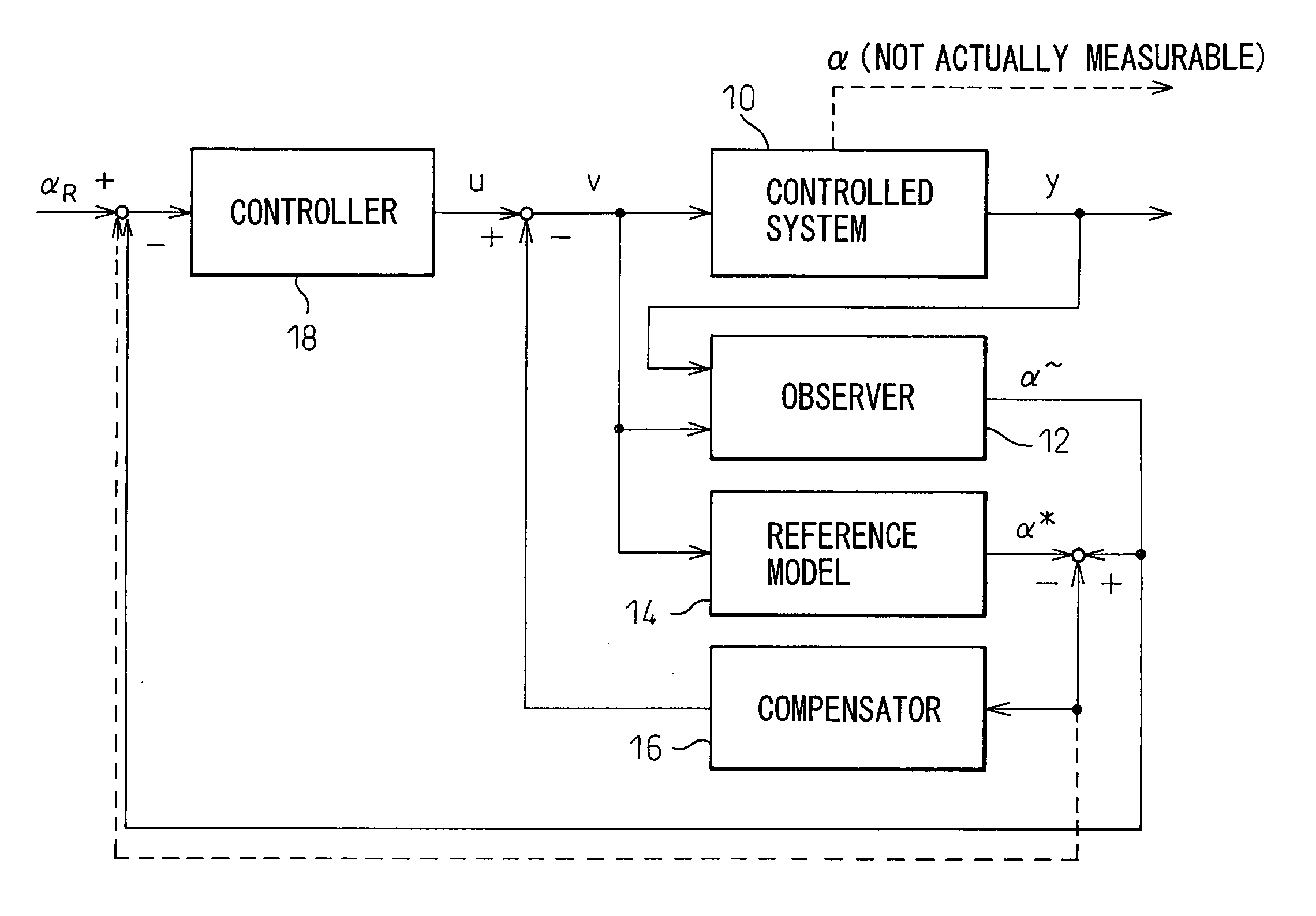
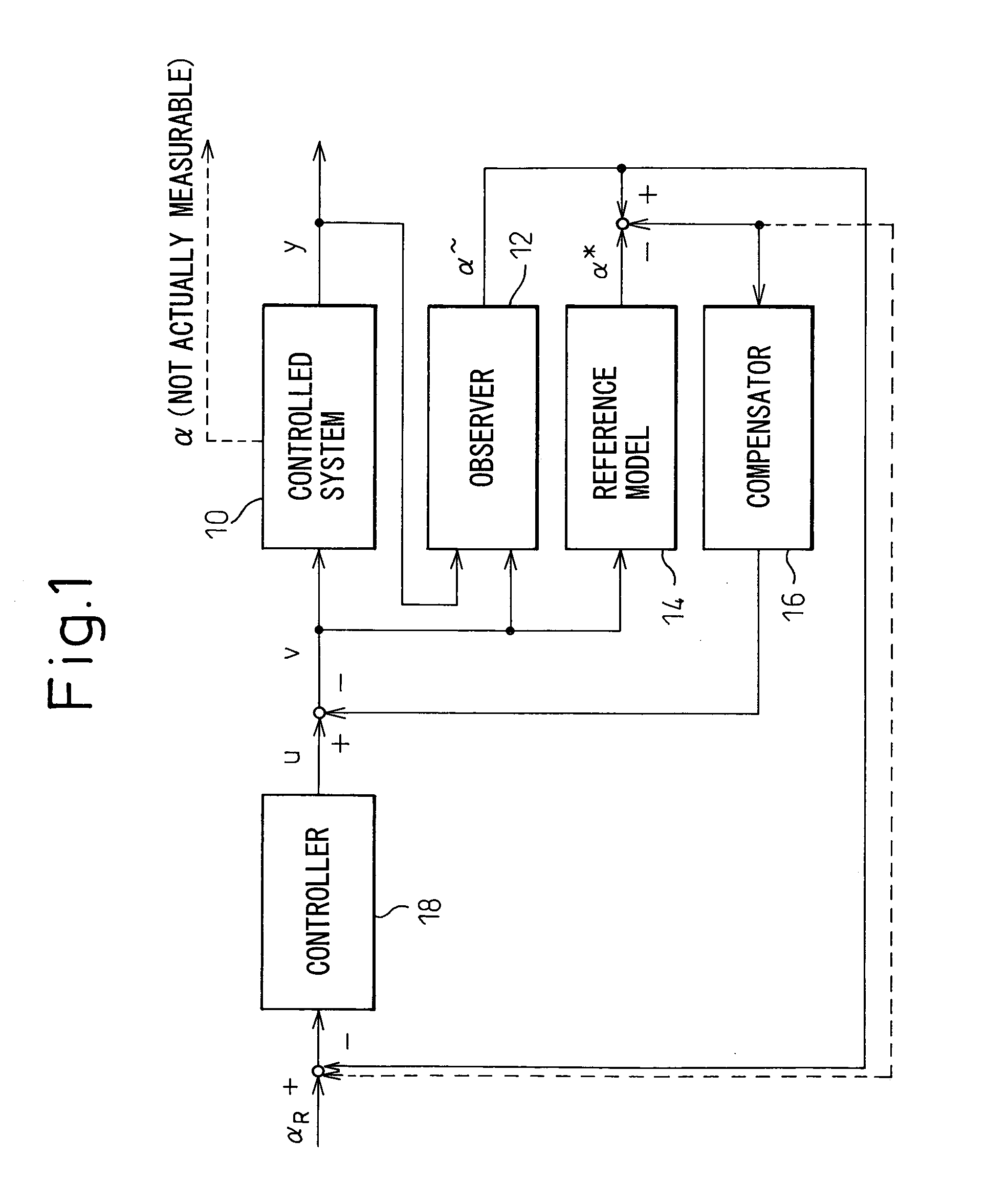
[0055]Referring to the drawings, FIG. 1 is a block diagram showing the configuration of a control device according to the present invention. The control device of the present invention includes an observer (i.e., a state-variable estimating section) 12 for estimating a state variable α (which is not actually measurable) representing the internal state of a controlled object or system 10 as a particular part in a machine to be actually controlled, so as to output the estimated state variable α˜; a reference model 14 for outputting an ideal controlled variable α* which defines an ideal response value for the controlled system 10; a compensator 16 for calculating a compensation value for correcting a control input “u” for the controlled system 10, based on the differen...


PUM


Abstract

A control device for controlling the motion of a movable part in a machine while suppressing vibration generated in the movable part. The control device includes a state-variable estimating section for estimating a state variable of a controlled system in the machine and outputting an estimated state variable; a reference model for outputting an ideal controlled variable for the controlled system; a compensator for calculating a compensation value for correcting a control input for the controlled system, based on a difference between the estimated state variable and the ideal controlled variable; and a feedback control section for determining the control input, based on a deviation between a desired command value and one of the estimated state variable and the ideal controlled variable. A corrected control input obtained by correcting the control input determined through the feedback control section by using the compensation value calculated through the compensator is input to the controlled system as well as to the state-variable estimating section and the reference model.

Description

BACKGROUND OF THE INVENTION[0001]1. Field of the Invention[0002]The present invention relates to a control device for controlling the motion of a movable part in a machine and, more particularly, to a control device capable of suppressing vibration generated in the movable part.[0003]2. Description of the Related Art[0004]Generally, a movable part in a machine, such as an industrial machine, a machine tool, a robot, or the like, is driven by a driving source through various transmission mechanisms, and the position and speed of the movable part are controlled as in a controlled system. In this connection, the mechanical components, such as the transmission mechanism, interposed between the driving source and the movable part have relatively low rigidity. Accordingly, in a case where the movable part is moved at high speed and stopped at a target position, the movable part tends to vibration easily.[0005]As an example, an actuator for a robot arm will be examined. FIG. 21 shows, by w...

Claims


Application Information

Patent Timeline
Patent Type & Authority Patents(United States)
IPC IPC(8): G05B13/02B23Q11/00F16F7/00F16F7/10F16F15/02G05D19/00G05D19/02
CPCG05D19/02F16F7/1005F16F15/02B60G2202/25B60G2400/206B60G2600/09B60G2600/124B60G2600/1873B60G2800/162B60G2600/1872G05B13/04
Inventor NIHEI, RYOKATO, TETSUAKIARITA, SOICHI
Owner FANUC LTD
Why Eureka
Try Eureka