Method for controlling an operating condition of a vehicle engine

a technology for operating conditions and engine, applied in the direction of electric control, braking system, instruments, etc., can solve the problems of complex combination of software tabular and surface data, difficult and high dependence on hard-to-achieve precise measurement of engine operating parameters

Active Publication Date: 2007-02-20
FCA US
View PDF7 Cites 45 Cited by
  • Summary
  • Abstract
  • Description
  • Claims
  • Application Information

AI Technical Summary

Problems solved by technology

Conventional airflow models for use in computer control of vehicular engines suffer from the fact that gas densities and volumetric efficiencies used in control algorithms are not constant, thereby requiring use of complex error correction factors.
Such correction factors, in turn, are highly dependent on hard-to-achieve precise measurements of engine operating parameters, such as manifold absolute pressure.
Additionally, prior approaches require complex combinations of software tabular and sur

Method used


Image

  • Method for controlling an operating condition of a vehicle engine
  • Method for controlling an operating condition of a vehicle engine
  • Method for controlling an operating condition of a vehicle engine

Examples


Embodiment Construction

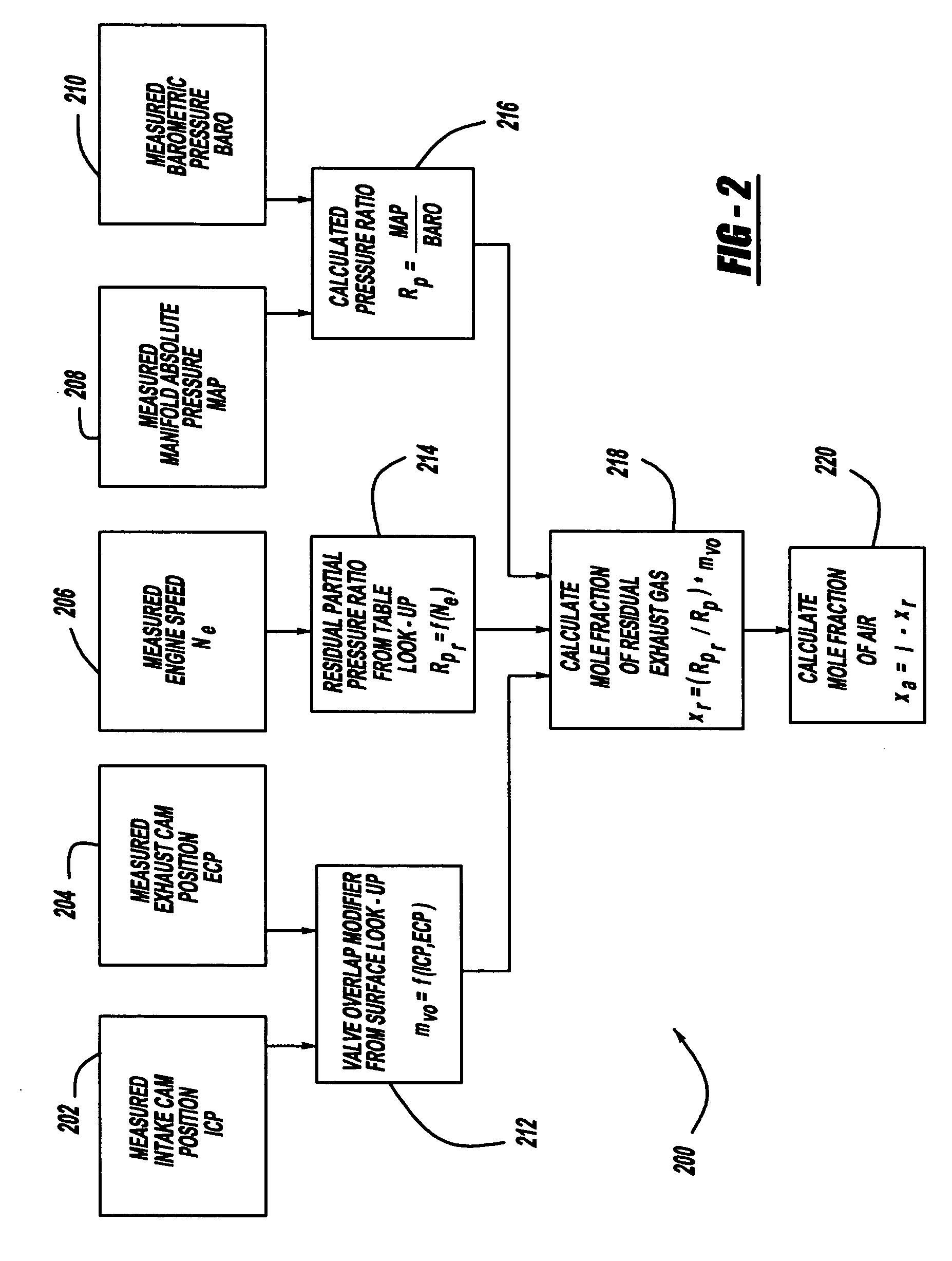
[0015]The method of the invention is based on model refinements to both volumetric efficiency and gas density. We begin by defining the volumetric efficiency as the ratio of the actual cylinder volume to the cylinder volume upon intake valve closure for that cylinder. This definition is consistent with the classical definition of a mole fraction and therefore the refined definition of volumetric efficiency is equal to the mole fraction of air in the cylinder. Neglecting fuel, we presume that the contents of a selected cylinder upon closure of the intake valve are limited to air and exhaust gas residual. Hence, the mole fraction of the residual exhaust gas is simply 1—the mole fraction of air. Conversely, the mole fraction of air is given by 1—the mole fraction of the residual exhaust gas. Hence, since the method uses a model of the residual exhaust, the mole fraction of air is calculated from the determined mole fraction of the residual exhaust.

[0016]Knowing the relative amounts of ...


PUM


Abstract

A residual ratio factor characterizing the amount of residual exhaust gas left in a selected cylinder at the end of a piston intake stroke is determined from tabular and surface models based on previously gathered dynamometer data from a test vehicle at various engine speeds. The residual ratio factor is then used to calculate the mole fractions of air and residual exhaust gas in the selected cylinder, which, in turn, are used to determine mass airflow at an engine intake port at the end of the intake stroke. The mass airflow can then be used to derive further models for determining an engine operating parameter, such as fuel/air ratio, required for achieving at preselected vehicle operating condition.

Description

FIELD OF THE INVENTION[0001]The present invention generally relates to vehicle engine control systems. More specifically, the invention pertains to fueling adjustments based on airflow models derived from test vehicles dynamometer data.BACKGROUND OF THE INVENTION[0002]Conventional airflow models for use in computer control of vehicular engines suffer from the fact that gas densities and volumetric efficiencies used in control algorithms are not constant, thereby requiring use of complex error correction factors. Such correction factors, in turn, are highly dependent on hard-to-achieve precise measurements of engine operating parameters, such as manifold absolute pressure. Additionally, prior approaches require complex combinations of software tabular and surface data to properly calibrate the controller to estimate normally unmeasured parameters, such as cylinder temperature.[0003]The complexity of cylinder temperature calibration requires large amounts of time in specialty dynamome...

Claims


Application Information

Patent Timeline
IPC IPC(8): B60T7/12F02B75/02
CPCF02D41/1445F02D41/145F02D41/18F02M25/0752F02D35/024F02D13/0219F02D35/026F02D41/0007F02D41/0062F02D2041/001F02D2041/0067F02D2200/0402F02D2200/0406F02D2200/703F02D13/0261F02M26/01
Inventor VICK, ROGER KPRUCKA, MICHAEL JCOATESWORTH, TIMOTHY AKRAMER, DENISE MDIVALENTIN, EUGENIOOHL, GREGORY L
Owner FCA US
Why Eureka
Try Eureka