Adjustable shuttle stop apparatus

a technology of stopper and stop plate, which is applied in the field of stopper, can solve the problem of not being able to position the material

Inactive Publication Date: 2007-02-27
HEM
View PDF27 Cites 20 Cited by
  • Summary
  • Abstract
  • Description
  • Claims
  • Application Information

AI Technical Summary

Benefits of technology

[0015]Preferably, in the third embodiment, the apparatus further comprises a spring engaging the shaft and biasing the shaft longitudinally with respect to the sleeve for eliminating play in the threaded connection between the shaft and sleeve. The third embodiment may also comprise a switch and a cam rotatable by the prime mover and having a cam lobe thereon for engaging the switch when the cam is in a predetermined position. This predetermined position preferably corresponds to a longitudinal mid-point of the shaft. The switch is connected to the controller for the shuttle vise so the system can be reset with the location of the shaft known.

Problems solved by technology

However, in cases where the cut length of the material may be critical this prior art saw may not be able to position the material in the cutting position accurately enough to insure that the cut length is within the desired tolerances.
The problem has to do with the straightness of the material, surface imperfections, and / or flexibility of the material and the deflection thereof when clamped by the shuttle vise.
Obviously, if the movement of the shuttle vise can be greater than the cut length tolerances on the workpiece, this is very undesirable.

Method used


Image

  • Adjustable shuttle stop apparatus
  • Adjustable shuttle stop apparatus
  • Adjustable shuttle stop apparatus

Examples


Embodiment Construction

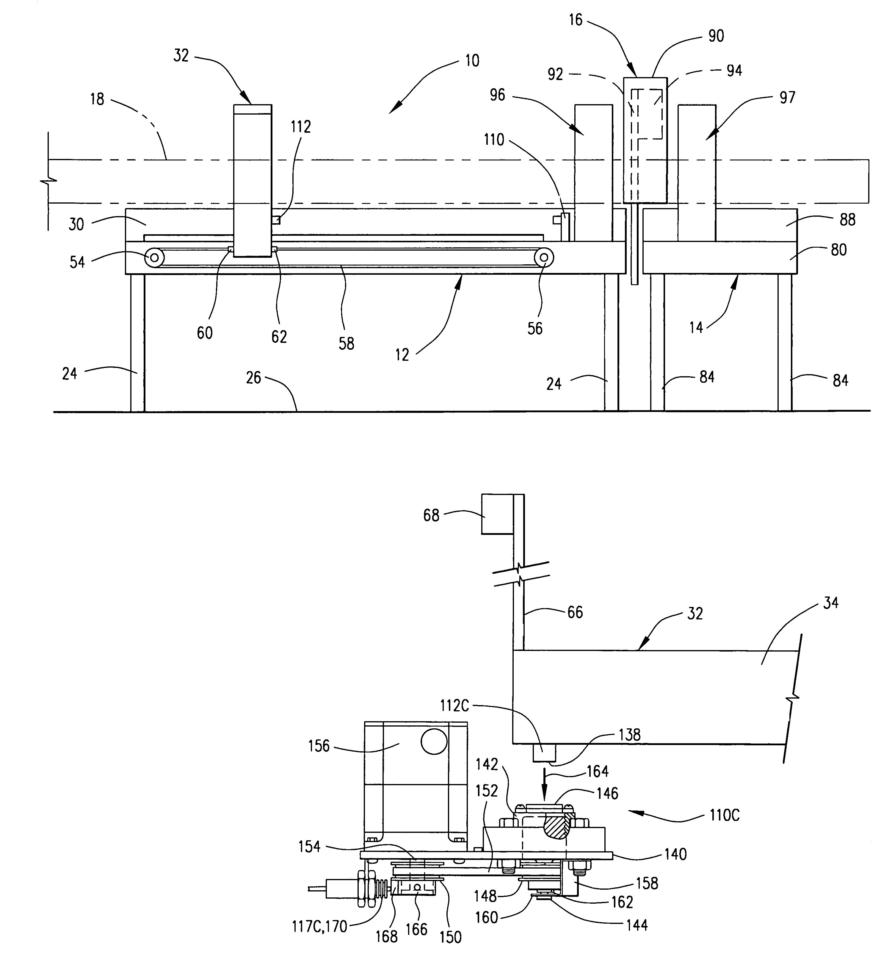
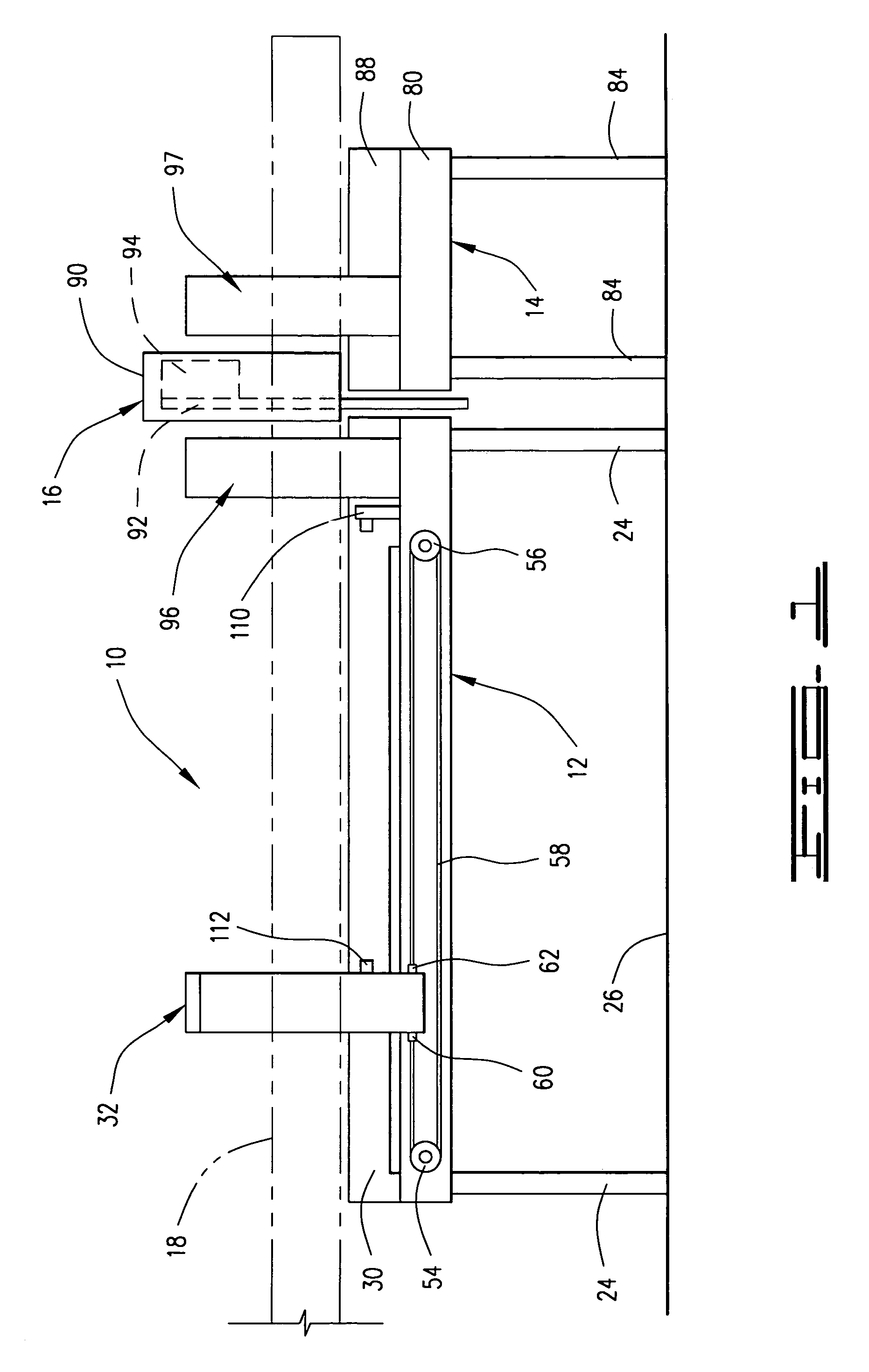
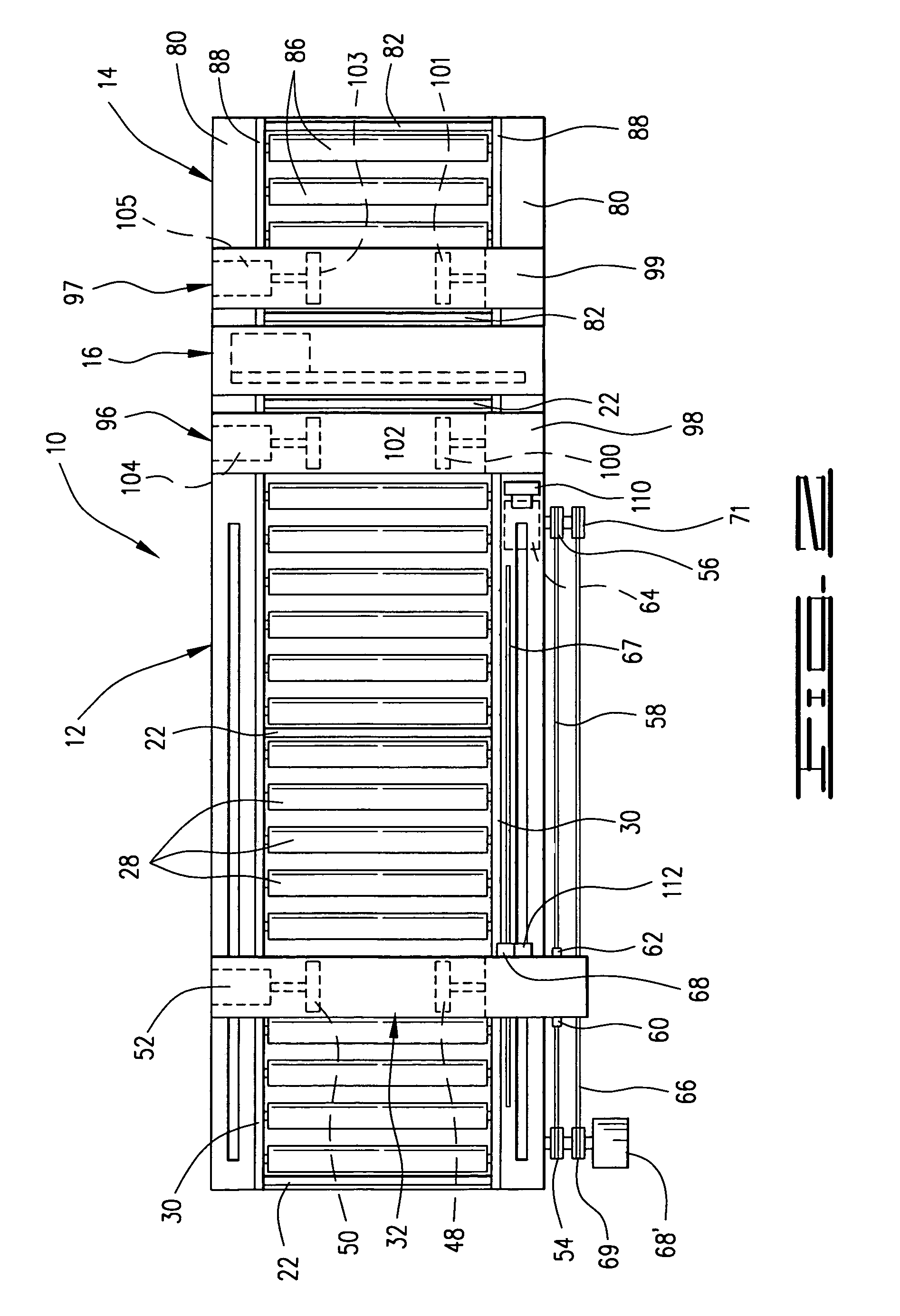
[0033]Referring now to the drawings and more particularly to FIGS. 1–3, the band saw apparatus with adjustable shuttle stop of the present invention is shown and generally designated by the numeral 10. Apparatus 10 comprises a horizontally disposed feed conveyor 12 and a horizontally disposed receiving conveyor 14. A band saw 16 is disposed between feed conveyor 12 and receiving conveyor 14 and is adapted for cutting workpiece 18 formed of elongated material. Workpiece 18 includes a single piece or multiple pieces bundled and / or stacked together. Band saw 16 will normally be connected to receiving conveyor 14.

[0034]Feed conveyor 12 generally comprises a pair of side rail supports 20 interconnected by a plurality of cross members 22. Side rail supports 20 are supported on a plurality of legs 24 above a ground surface 26.

[0035]Feed conveyor 12 also has a plurality of longitudinally spaced, transversely extending rollers 28 rotatably mounted on a pair of longitudinally extending roller...


PUM

PropertyMeasurementUnit
distanceaaaaaaaaaa
distanceaaaaaaaaaa
lengthaaaaaaaaaa

Abstract

A adjustable shuttle stop apparatus for use in controlling feeding of material to a machining operation on a machine tool, such as a band saw. The apparatus comprises a feed conveyor, a band saw adjacent to the feed conveyor, a shuttle vise movably disposed on the feed conveyor, and an adjustable stop on the feed conveyor for adjusting a distance between the stop and the shuttle vise and for stopping the shuttle vise at the cutting position. The adjustable stop compensates for undesired movement of the shuttle vise caused by clamping the workpiece such that the distance between the stop and the shuttle vise remains substantially constant. This allows for a consistent cut length of the workpiece on subsequent cutting cycles. Different embodiments of the adjustable stop are disclosed along with a method of use of the apparatus.

Description

[0001]This a divisional of application Ser. No. 09 / 885,176, filed Jun. 21, 2001now U.S Pat. No. 6,698,159.BACKGROUND OF THE INVENTION[0002]1. Field of the Invention[0003]This invention relates to stops used in controlling the feeding of material as a workpiece to a machining operation, such as cutting a length of the material on a band saw, and more particularly, to an adjustable stop which compensates for undesired movement of the workpiece. The stop is illustrated in conjunction with a shuttle vise on a band saw, but the stop may be used in other applications, such as the feeding of material to a punch press, etc.[0004]2. Description of the Prior Art[0005]Machines for cutting material, such as large band saws which are used to cut workpieces formed of elongated materials, are well known in the art. The workpiece material is positioned on a feed conveyor adjacent to the saw blade and moved into a cutting position under the saw blade by a shuttle vise which is moved to a clamping po...

Claims


Application Information

Patent Timeline
Patent Type & Authority Patents(United States)
IPC IPC(8): B26D5/20B23D47/04B23D55/04B27B27/02
CPCB23D47/04B27B27/02B23D55/043Y10T83/445Y10T83/446Y10T83/4465Y10T83/4513Y10T83/4556Y10T83/4597Y10T83/461Y10T83/4632Y10T83/4645Y10T83/6531Y10T83/6532
Inventor HARRIS, GERALD R.NEALL, TIMOTHY M.
Owner HEM
Why Eureka
Try Eureka