Pulverizer real-time monitoring system

a real-time monitoring and pulverizer technology, applied in the field of pulverizers, can solve the problems of limiting access to the internal components that are most susceptible to aggressive wear, damage and/or degradation, and high cost of down time that interrupts the process

Active Publication Date: 2007-02-27
ENG CONSULTANTS GROUP
View PDF6 Cites 61 Cited by
  • Summary
  • Abstract
  • Description
  • Claims
  • Application Information

AI Technical Summary

Problems solved by technology

The grinding or pulverizing equipment is usually exposed to severe conditions both due to the nature of the materials and the restraints of the environment.
These equipment considerations are likely to include the following: abrasive raw materials; high energy input requirement; toxicity (leak proof containment); vibration; explosive or combustible characteristics; large volume / mass rates with low profit margin processes; and around the clock / long term operations.
These conditions often mandate the construction of the equipment such that thick-walled, abrasion resistant, high strength materials are required to confine the process materials within a grinding zone thus limiting access to the internal components that are most susceptible to aggressive wear, damage and / or degradation.
With many of these processes being quasi-continuous, any down time that interrupts the process is very costly and a major consideration in the economic viability of the plant utilizing the equipment.
This history-based practice can have significant error with avoidable costs from the premature expenditure of manpower and replacement of expensive parts that have remaining life.
Worse yet, the reactive maintenance could be after-the-fact with premature failure having been due to accelerated wear or other unanticipated damage.
This latter situation normally incurs major production shortfalls with unacceptable maintenance costs and delays in return to service due to the short-term parts acquisition and / or the unscheduled manpower requirements (i.e., overtime or contractor augmented work force).
However, prior art data collection devices have not been able to format the data in a direct and user-friendly format.
Moreover, testing in this manner was done on a piecemeal basis and a real-time analysis of the operation of the pulverizing equipment was not available.
Moreover, no known systems allow for system-wide monitoring of pulverizer units utilized in production settings or other industrial applications.

Method used


Image

  • Pulverizer real-time monitoring system
  • Pulverizer real-time monitoring system
  • Pulverizer real-time monitoring system

Examples


Embodiment Construction

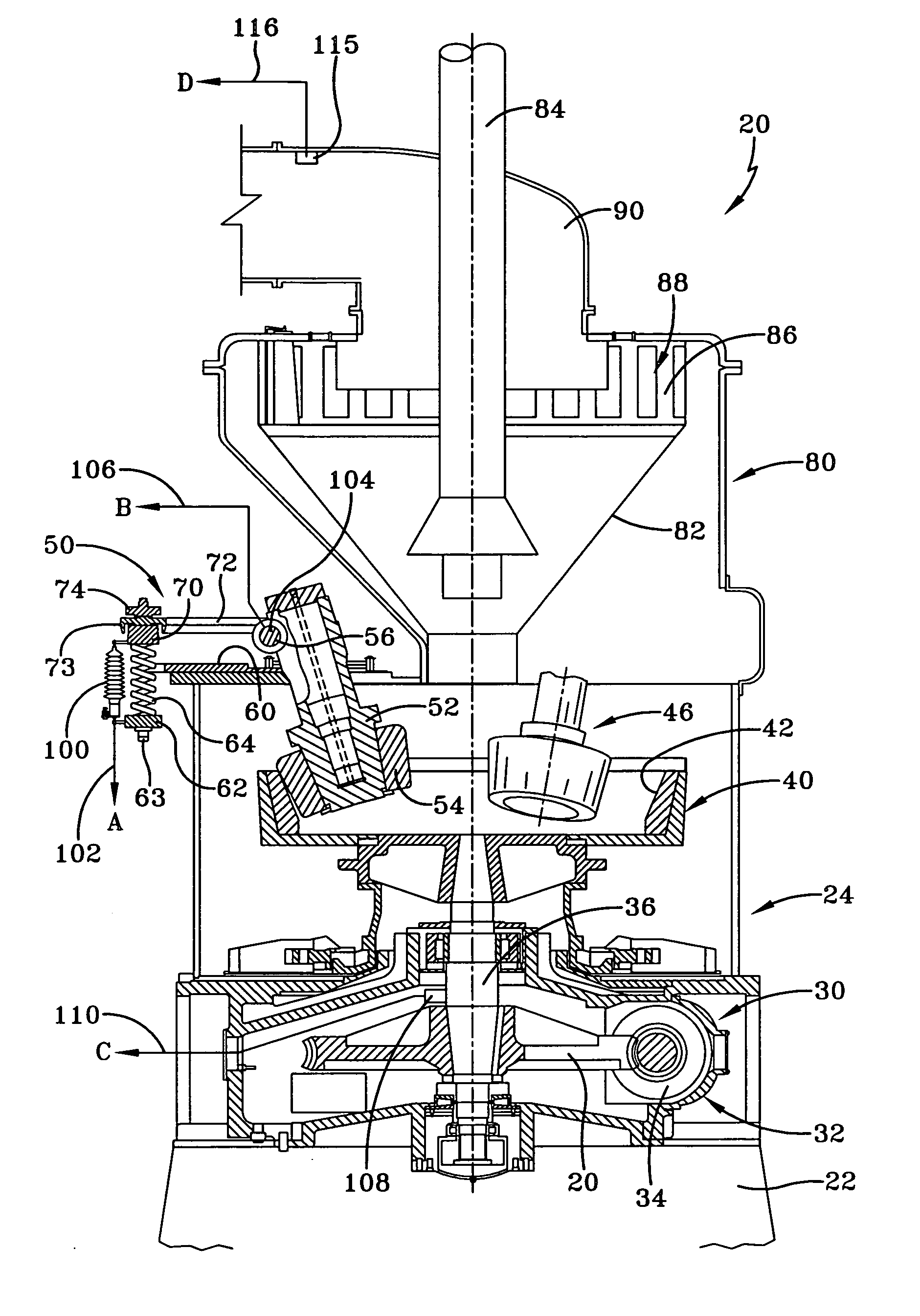
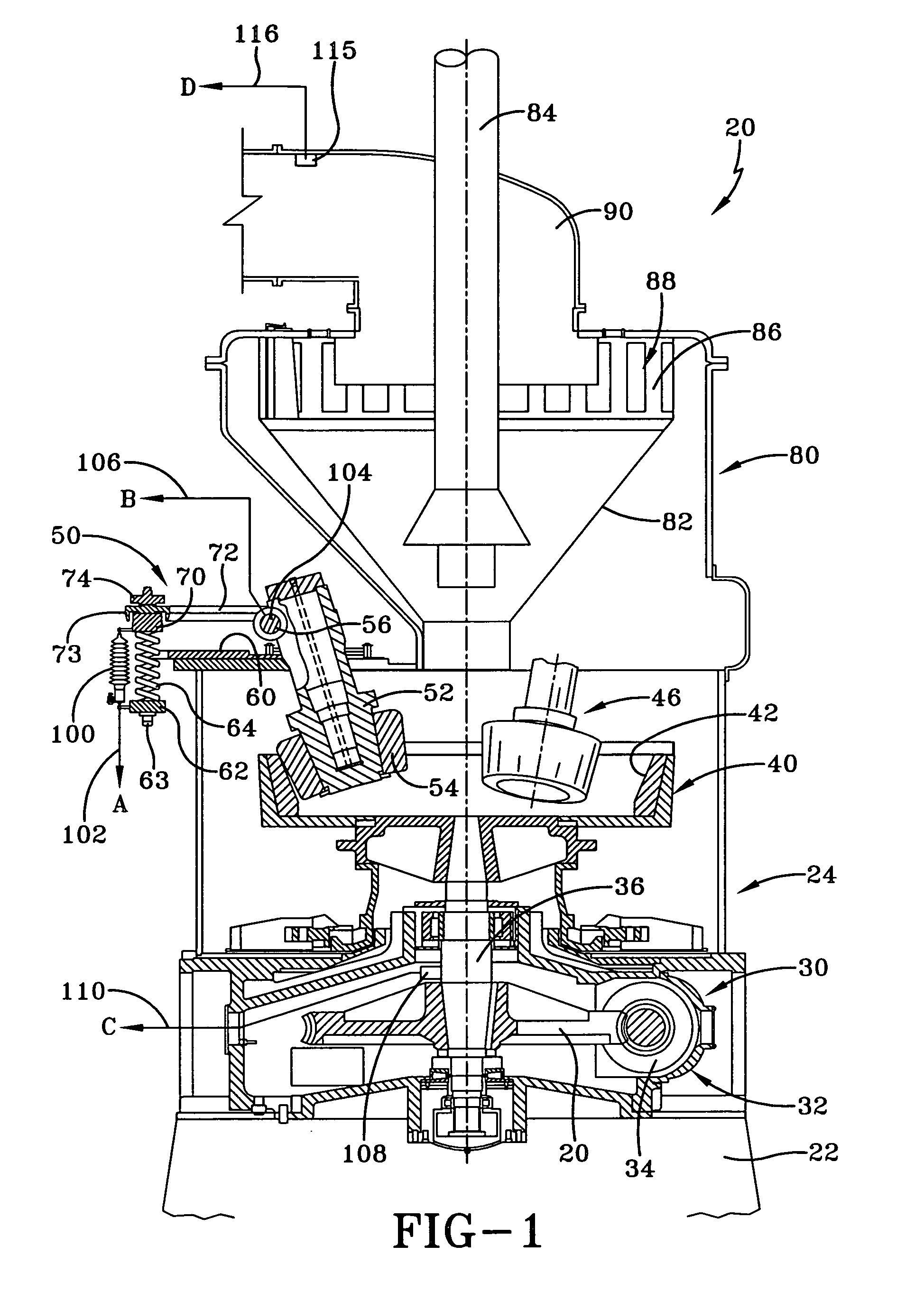
[0021]Referring now to the drawings, and in particular to FIG. 1, it can be seen that a pulverizer according to the present invention is designated generally by the numeral 20. The pulverizer 20 is an exemplary unit and it will be appreciated that the teachings herein are applicable to any grinding device which utilizes at least one grinding roll associated with a motor-driven bowl. In other words, expected variations in the structure of the exemplary pulverizer are inconsequential to the teachings of the invention. In any event, as such a pulverizer may be used to grind raw materials into finer or smaller particulate matter. Exemplary raw materials are coal, stone, metal ores, crystalline chemicals and the like. As used herein, the pulverizer is primarily associated with coal pulverizers utilized in conjunction with boiler systems and the like.

[0022]The pulverizer 20 is mounted upon and supported by a foundation 22. The pulverizer includes a mill housing 24 that is secured to the f...


PUM


Abstract

A pulverizer monitoring system is applicable to at least one pulverizer having a rotatable bowl assembly, and at least one journal assembly having a grinding roll positioned proximal the rotatable bowl assembly, wherein the grinding roll is deflected by the feedstock raw material forced under the roll during rotation of the rotatable bowl assembly. A position sensor is mounted to the journal assembly to detect an amount of deflection of the grinding roll and generates a position signal, wherein a data module is associated with each pulverizer so as to receive the position signal. A calculation engine is linked to each data module for the purpose of analyzing the position signal and other operational signals associated with the pulverizer and generating at least one characteristic pulverizer condition report. A web-based server is linked to the calculation engine to provide network access to the characteristic report(s), either real-time or historical trends. A user interface is provided with either the calculation engine and the web-based server to allow the custom setting of alarms and / or formats for the output associated with the characteristic report(s).

Description

TECHNICAL FIELD[0001]The present invention is generally related to pulverizers. More specifically, the present invention is related to monitoring equipment associated with a pulverizer. In particular, the present invention is related to a real-time monitoring system which generates various reports indicating the operational health of a pulverizer and / or a group of pulverizers and which also provides the ability to set alarm indications whenever a pulverizer is operating outside of predetermined criteria.BACKGROUND ART[0002]Many industrial processes require the grinding of materials to fine particles either as raw materials or as an intermediate or final product. The materials to be ground might include coal, stone, metal ores, crystalline chemicals, etc. The grinding or pulverizing equipment is usually exposed to severe conditions both due to the nature of the materials and the restraints of the environment. These equipment considerations are likely to include the following: abrasiv...

Claims


Application Information

Patent Timeline
Patent Type & Authority Patents(United States)
IPC IPC(8): B02C4/32
CPCB02C25/00B02C15/06
Inventor SANTUCCI, MICHAEL T.
Owner ENG CONSULTANTS GROUP
Why Eureka
Try Eureka