Constant-voltage power circuit with fold back current limiting capability

a constant-voltage power circuit and capability technology, applied in the direction of electric variable regulation, process and machine control, instruments, etc., can solve the problem of not being able to arbitrarily set the value of output current, and achieve the effect of reducing or eliminating

Inactive Publication Date: 2007-02-27
RICOH ELECTRONIC DEVICES CO LTD
View PDF5 Cites 55 Cited by
  • Summary
  • Abstract
  • Description
  • Claims
  • Application Information

AI Technical Summary

Benefits of technology

[0035]Accordingly, it is an object of the invention to provide a constant-voltage power circuit having most, if not all, of the advantages and features of similarly employed power circuits, while reducing or eliminating many of the aforementioned disadvantages.
[0036]It is another object to provide a constant-voltage power circuit incorporating an over-current protection circuit having a fold back current limiting capability operative through low input voltages, and capable of arbitrarily setting the values of current output.

Problems solved by technology

However, a difficulty with the circuit configuration of FIG. 4 is that the output current from the output transistor M101 is one half of the output current maximum under short-circuit conditions, and it is not feasible for the value of output current be set arbitrarily.

Method used


Image

  • Constant-voltage power circuit with fold back current limiting capability
  • Constant-voltage power circuit with fold back current limiting capability
  • Constant-voltage power circuit with fold back current limiting capability

Examples


first embodiment

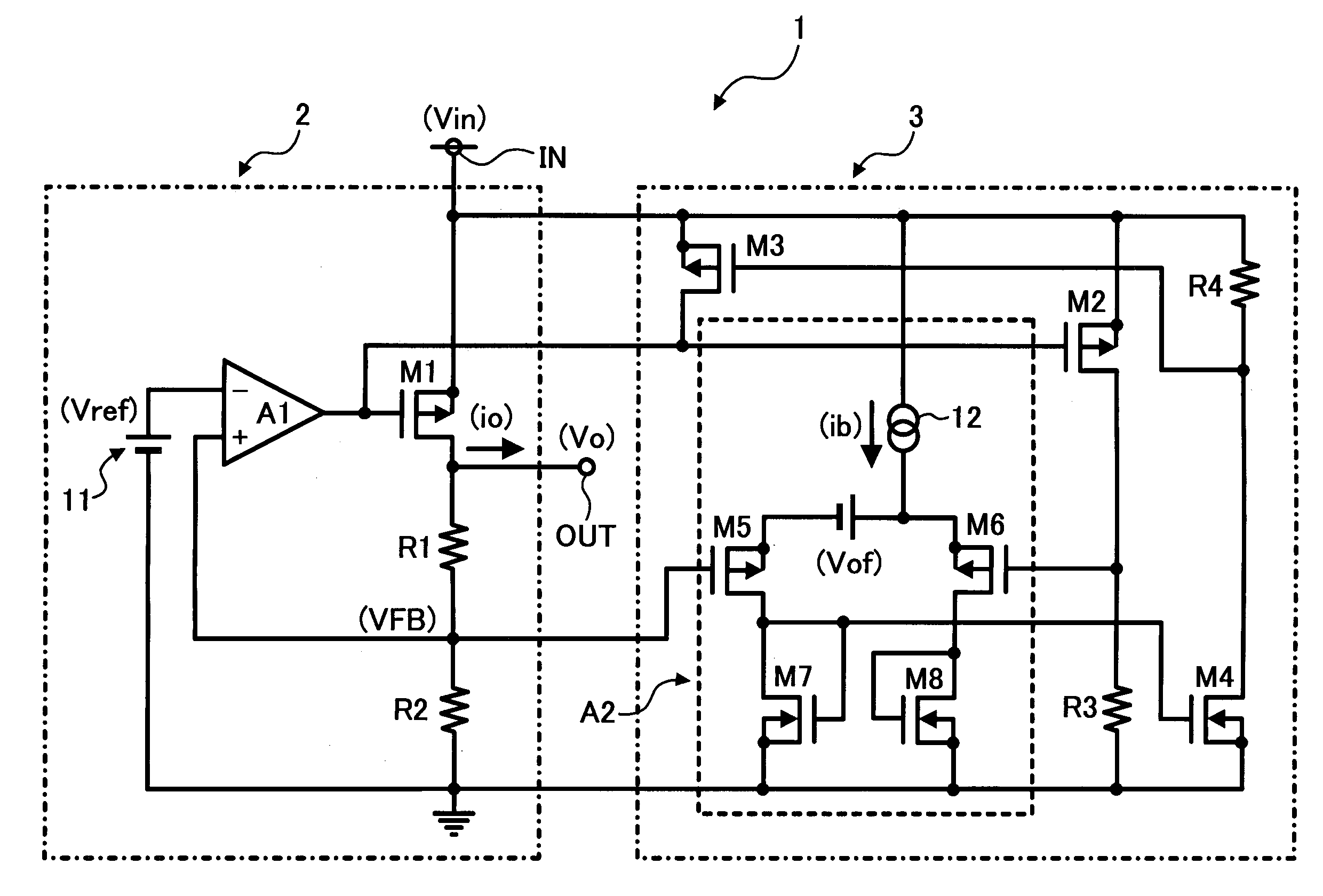
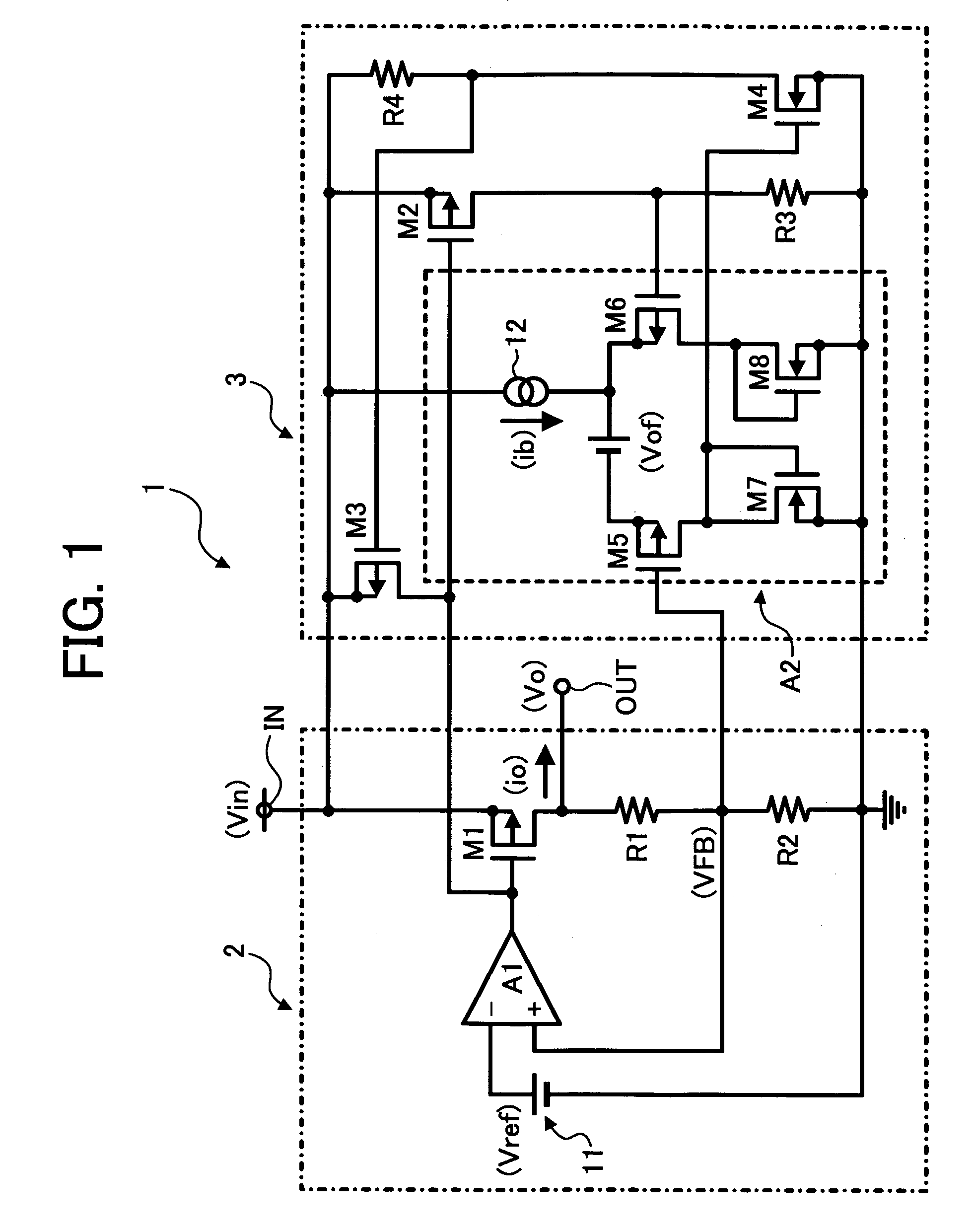
[0080]FIG. 1 is a diagrammatic circuit diagram illustrating a constant-voltage power supply circuit disclosed herein.

[0081]Referring to FIG. 1, a constant-voltage power supply circuit 1 is configured to convert an input voltage Vin, which is input to an input terminal IN, into a predetermined constant voltage, and subsequently output as an output voltage Vo from an output terminal OUT.

[0082]The constant-voltage power supply circuit 1 may be integrated to be a single IC (integrated circuit) device.

[0083]The constant-voltage power supply circuit 1 includes at least a constant-voltage circuit 2 configured to convert an input voltage Vin into a predetermined constant voltage to subsequently be output as an output voltage Vo from an output terminal OUT, and an over-current protection circuit 3 configured to have a fold back current limiting capability, in that this current limiting capability is characterized by the function of the protection circuit 3 such that, in the case when an out...

second embodiment

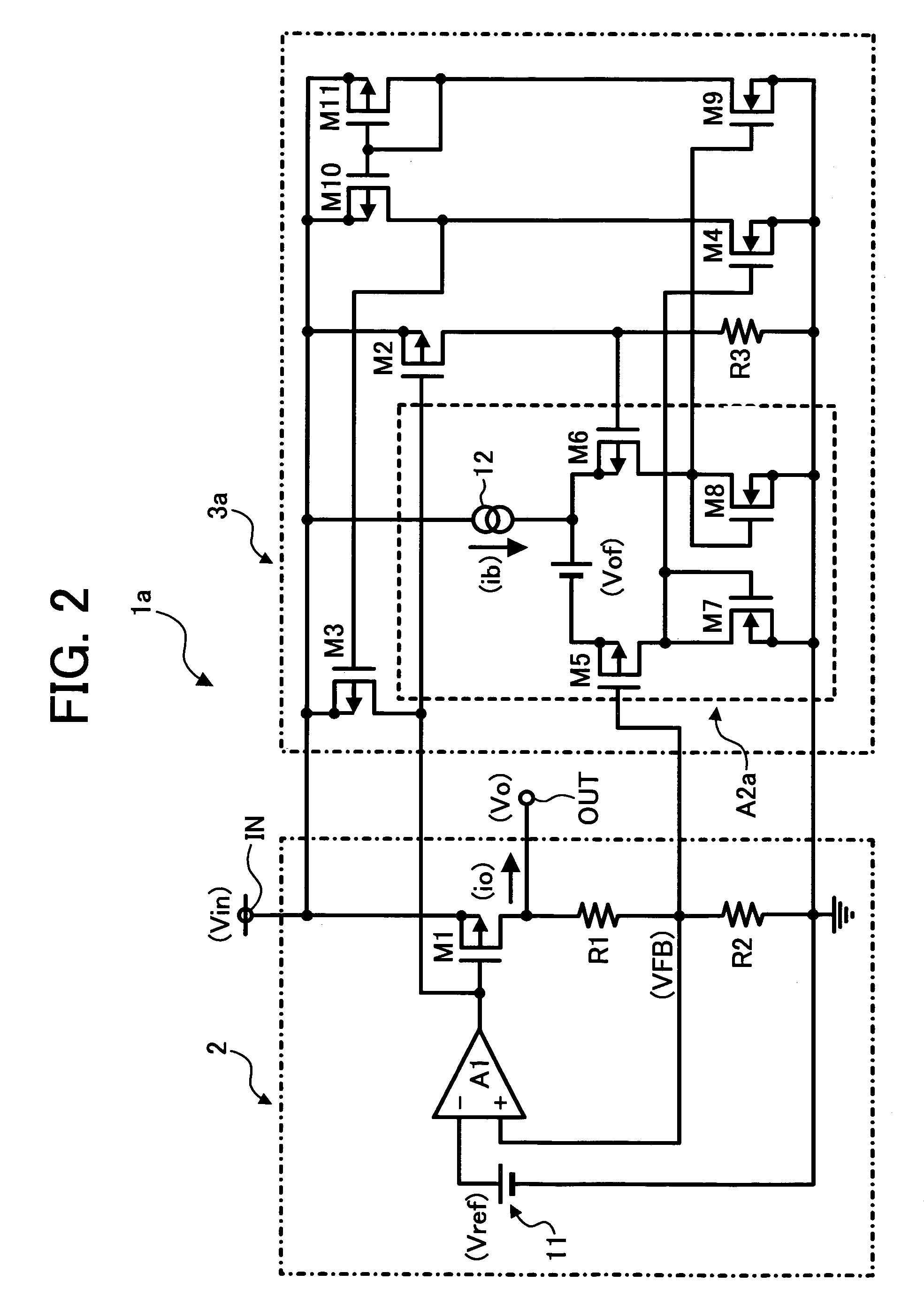
[0113]FIG. 2 is a diagrammatic circuit diagram illustrating a constant-voltage power supply circuit disclosed herein.

[0114]The components in the constant-voltage power supply circuit of FIG. 2 that are similar to those of the power supply circuit described earlier in reference to FIG. 1 are shown with identical numerical representations, and the description thereof is herein abbreviated for purposes of clarity.

[0115]The constant-voltage power supply circuit of FIG. 2 has a device structure similar to the power supply circuit of FIG. 1, with the exception that the resistor R4 of FIG. 1 is eliminated, and that NMOS transistors M9 and PMOS transistors M10 and M11 are appended, whereby NMOS transistors M7 and M4 constitutes a current mirror circuit and NMOS transistors M8 and M9 constitutes a further current mirror circuit.

[0116]Accordingly, there shown in FIG. 2 are a constant-voltage power supply circuit 1a and an over-current protection circuit 3a in place of the constant-voltage po...


PUM


Abstract

A constant-voltage power circuit incorporating an over-current protection circuit having a fold back current limiting capability operative through low input voltages, and being capable of arbitrarily setting current outputs. The constant-voltage power supply circuit is configured so that a voltage output with small amplitude from a differential amplifier circuit is subjected to amplitude expansion to be amplified to range fully from the ground potential approximately to the input voltage by means of an amplitude expansion circuit, which includes an inverter consisting of an NMOS transistor and a resistor, and that the voltage resulting from the amplitude expansion is subsequently input to the gate of a PMOS transistor configured to directly control an output transistor.

Description

[0001]This application claims priority to Japanese Patent Application No. 2005-132446, filed with the Japanese Patent Office on Apr. 28, 2005, the entire contents of which are hereby incorporated by reference.FIELD OF INVENTION[0002]The invention generally relates to constant-voltage power circuits, and more specifically to a constant-voltage power circuit incorporating an over-current protection circuit having a fold back current limiting capability operative through low input voltages.BACKGROUND OF INVENTION[0003]In order to implement overcurrent protection for constant-voltage power supply circuits employing series regulators, overcurrent protection circuits have been widely used such as, for example, a current limiting circuit configured to prevent a current output from exceeding a predetermined current, and an overcurrent protection circuit configured to limit a current output under short circuit conditions.[0004]The overcurrent protection circuit is characterized by the so-cal...

Claims


Application Information

Patent Timeline
Patent Type & Authority Patents(United States)
IPC IPC(8): G05F1/573
CPCH02H9/025G05F1/5735
Inventor ITOH, KOHZOHTANAKA, SHUNSEI
Owner RICOH ELECTRONIC DEVICES CO LTD
Why Eureka
Try Eureka