
Liquid crystal display device and liquid crystal display method

a liquid crystal display device and display device technology, applied in static indicating devices, non-linear optics, instruments, etc., can solve the problems of poor visibility of display devices, low production cost of stn type liquid crystal display devices, and inability to meet the needs of personal computers, etc., to reduce the degradation of image quality and limit the effect of image quality degradation

Inactive Publication Date: 2007-02-27
FUJITSU LTD
View PDF24 Cites 11 Cited by
  • Summary
  • Abstract
  • Description
  • Claims
  • Application Information

AI Technical Summary

Benefits of technology

[0014]An object of the present invention is to provide a liquid crystal display device and a liquid crystal display method, capable of reducing such image quality degradation that the outline portion of a displayed moving image is seen as a blur and thereby displaying a full image with limited degradation of the image quality.
[0016]In the liquid crystal display device of the first aspect, by setting the frequency in the data writing process for the active matrix panel at least twice higher than the frame frequency (not to be lower than 120 Hz) and completing the data writing process and the data erasing process for the active matrix panel within one frame time, time taken for transmission of light through the coloring member is made no more than a half of one frame time. Hence, the coloring member is in a non-light-transmitting state in a period of not shorter than a half of one frame, and the blurred outline section of a moving image is reduced compared with a conventional example, thereby reducing degradation of the image quality.
[0018]Accordingly, upon the completion of the data writing process in one frame, the data erasing process is started, and upon the completion of this data erasing process, the data writing process for the next frame is started, thereby making it possible to readily control the data writing process and the data erasing process.
[0019]A liquid crystal display device of the third aspect of the present invention is based on the first aspect, and provides a period during which neither the data writing process nor the data erasing process is performed. Accordingly, time taken for transmission of light through the coloring member is further shortened and degradation of the image quality is further reduced, thereby achieving a further improvement in the image quality.
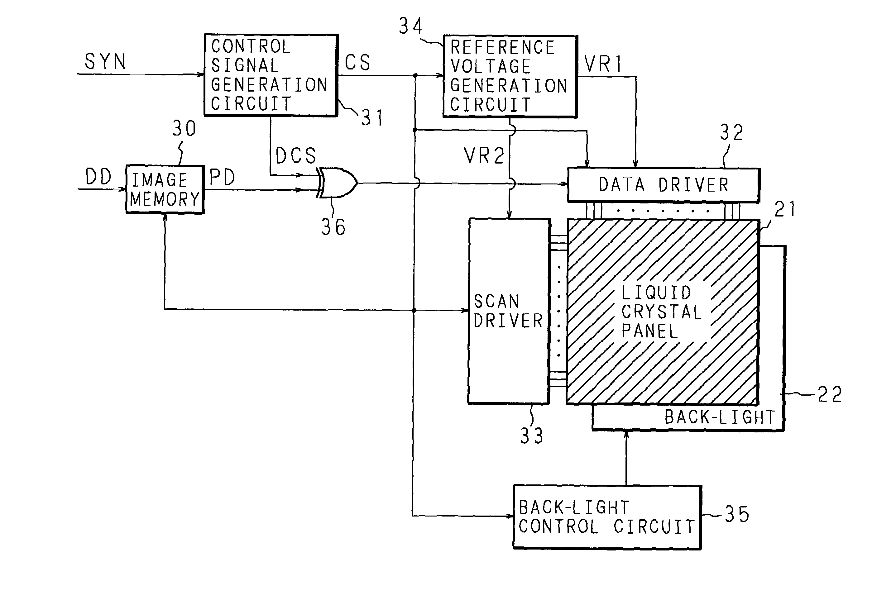
[0020]A liquid crystal display device of the fourth aspect of the present invention is based on any one of the first through third aspects, and comprises a back-light for irradiating white light on the coloring member and a back-light controller for controlling the back-light to be turned on or off according to the data writing process and the data erasing process. Since the liquid crystal display device of the fourth aspect controls the back-light as a light source to be turned on or off according to the data writing process and the data erasing process, the back-light is turned on only in a necessary period so as to reduce the consumption of power.

Problems solved by technology

Although the reflection type liquid crystal display devices have poor visibility resulting from the reflected light amount varying depending on environmental conditions, they have been widely used as monochrome (such as black and white) display devices for portable calculators, watches, etc. because of their low costs.
However, they are not suitable as display devices of personal computers displaying a multi-color or full-color image.
The STN type liquid crystal display devices have comparatively low production costs, but they are not suitable for the display of a moving image because they are susceptible to crosstalk and comparatively slow in the response rate.
For this reason, in the TFT-TN type liquid crystal display devices, a lot of power is consumed by the back-light, and there would be a problem when used with a battery power source.
Moreover, the TFT-TN type liquid crystal display devices have other problems including a low response rate, particularly in displaying half tones, a narrow viewing angle, and a difficult color balance adjustment.
With the currently-used liquid crystal display devices, however, even if images are displayed at a high rate, the liquid crystal display device reaches its limit in displaying around 40 images per second.
If full moving images are displayed at a higher rate, for example, at a rate of 60 images per second, the liquid crystal molecules can not act sufficiently, resulting in blurred images.
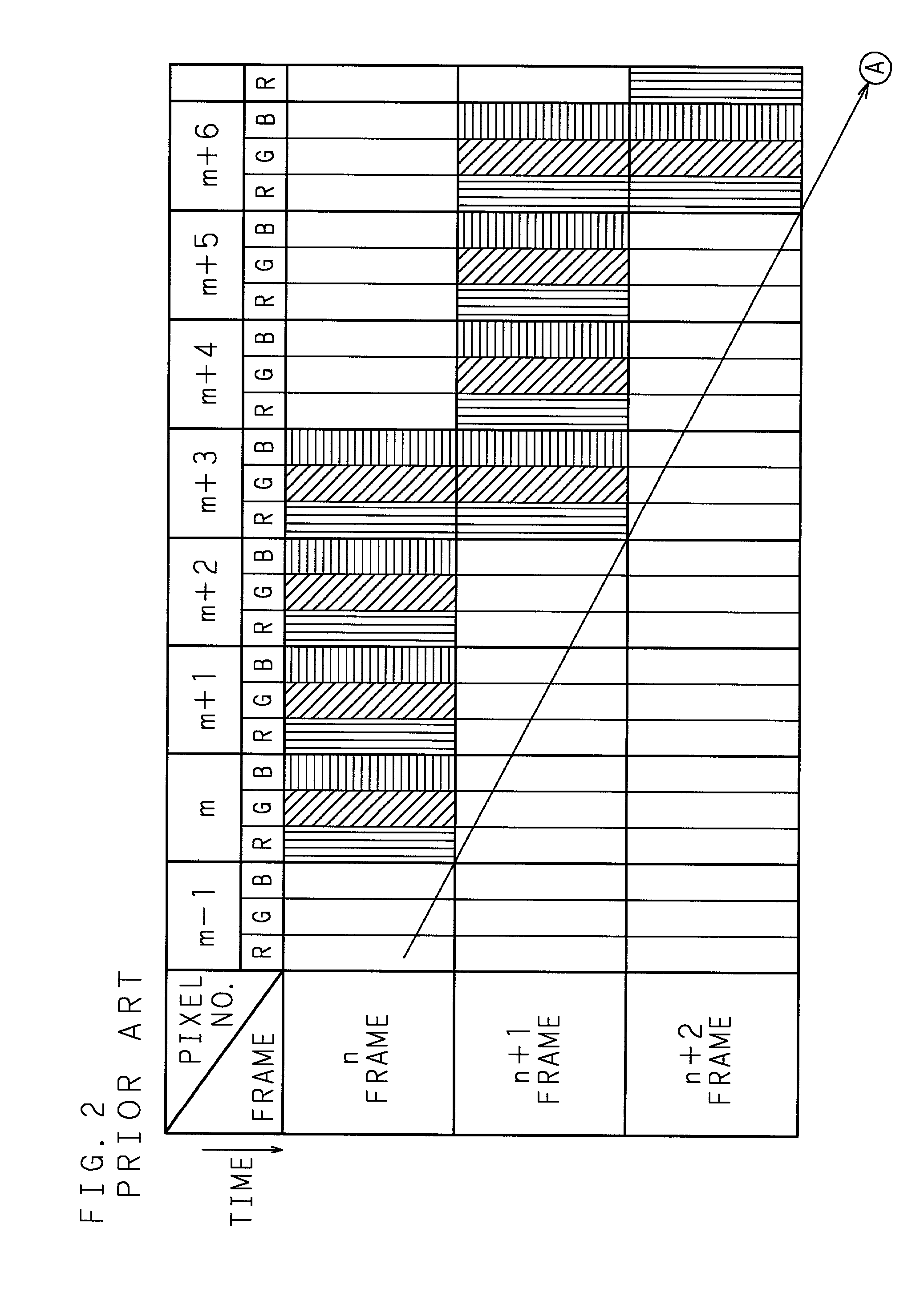
However, in this simple matrix type, since writing of each line is carried out until the liquid crystal molecules have come to a completely still state, it takes 16.6 milliseconds ( 1 / 60 second) or more to display one image and consequently a full moving image display can not be achieved.
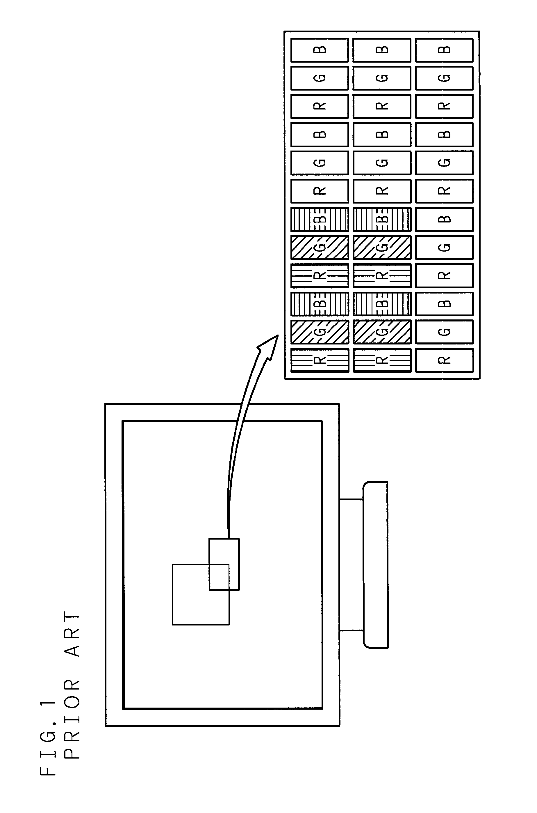
Moreover, as the moving speed increases, the blur of the outline portion becomes more noticeable, resulting in degradation of the image quality.
Hence, when this display device is used as a multimedia display device for displaying moving images, it causes a problem that degradation of the image quality occurs in displaying moving images.
However, when an image moves at an extremely high rate and the human's eyes can follow the moving image, degradation of the image quality as shown in FIG. 3 will be observed.

Method used


Image

  • Liquid crystal display device and liquid crystal display method
  • Liquid crystal display device and liquid crystal display method
  • Liquid crystal display device and liquid crystal display method

Examples


first embodiment

(First Embodiment)

[0075]FIG. 7 is an illustration showing a drive sequence according to the first embodiment, and FIG. 8 is an illustration showing a visualized state of a moving image displayed by drive according to the first embodiment.

[0076]In the first embodiment, one frame is divided into two sub-frames, namely the first sub-frame and the second sub-frame, and data writing is performed in the leading first sub-frame and data erasure (i.e., black display) is implemented in the succeeding second sub-frame. During the data writing and the data erasure, the back-light 22 is kept in the “ON” state (stationary lighting).

[0077]Consequently, as shown in FIG. 8, in comparison with FIG. 3 illustrating a conventional example, the range in which the outline portion is displayed as a blur becomes narrower and the area where degradation of the image quality occurs is reduced, thereby improving the image quality.

second embodiment

(Second Embodiment)

[0078]FIG. 9 is an illustration showing a drive sequence according to one example of the second embodiment. In the second embodiment, one frame is divided into two sub-frames, namely the first sub-frame and the second sub-frame, and data writing is performed in the leading first sub-frame and data erasure (i.e., black display) is implemented in the succeeding second sub-frame. In this case, each of the first and second sub-frames is divided into a leading address period and a succeeding retention period, and the data to be displayed on the liquid crystal panel 21 is written in the leading address period of the first sub-frame. After the writing is complete, the data is held during the succeeding retention period, and then the written data is erased in the leading address period of the second sub-frame. After the erasure is complete, the erased state is kept during the succeeding retention period of the second sub-frame.

[0079]Lighting patterns of the back-light 22 ...

third embodiment

(Third Embodiment)

[0081]FIG. 11 is an illustration showing a drive sequence according to the third embodiment. The data writing process and data erasing process in the third embodiment are the same as those in the above-described second embodiment. Accordingly, data writing is performed in the address period of the first sub-frame and data erasure is executed in the address period of the second sub-frame. The back-light 22 is turned on only in the retention period of the first sub-frame to display the written data.

[0082]FIG. 12 is an illustration showing a visualized state of a moving image displayed by drive according to the third embodiment. In comparison with the conventional example, the range in which the outline portion is seen as a blur becomes narrower and the area where degradation of the image quality occurs is reduced, thereby improving the image quality. Moreover, in comparison with the first embodiment, since the time during which the back-light 22 is in the “ON” state ...


PUM


Abstract

In a liquid crystal display device which is constructed by sealing a liquid crystal having spontaneous polarization in an active matrix panel including a coloring member and displays an image on a frame by frame basis by repeating a data writing process and a data erasing process for the active matrix panel, the frequency in the data writing process is set at least twice higher than a frame frequency and the data writing process and the data erasing process are completed within one frame time so that time taken for transmission of light through the coloring member is not more than a half of one frame time. The coloring member is in a non-light-transmitting state during a period of not shorter than a half of one frame, and the blurred outline section of a moving image is reduced.

Description

BACKGROUND OF THE INVENTION[0001]The present invention relates to a liquid crystal display device and liquid crystal display method, and more specifically to a color liquid crystal display device and color liquid crystal display method using a liquid crystal having spontaneous polarization.[0002]The liquid crystal display devices are mainly classified into the reflection type and the transmission type. In the reflection type liquid crystal display devices, light rays incident on the front face of a liquid crystal panel are reflected by the rear face of the liquid crystal panel so that an image is visualized by the reflected light. In the transmission type liquid crystal display devices, an image is visualized by transmitted light from a light source (back-light) provided on the rear face of the liquid crystal panel. Although the reflection type liquid crystal display devices have poor visibility resulting from the reflected light amount varying depending on environmental conditions,...

Claims


Application Information

Patent Timeline
IPC IPC(8): G09G3/36G09G3/20G02F1/133G09G3/34
CPCG09G3/3406G09G3/3651G09G2310/0237G09G2330/021G09G2310/061G09G2310/08G09G2320/0261G09G2310/024G02F1/141
Inventor MAKINO, TETSUYAYOSHIHARA, TOSHIAKISHIROTO, HIRONORIKIYOTA, YOSHINORI
Owner FUJITSU LTD
Learn More