Laser video projector having multi-channel acousto-optic modulator, and method and circuit for driving the same

a laser video projector and multi-channel technology, applied in the field of laser video projectors, can solve the problems of limited laser focus, and difficult for the conventional laser video projector to process video images with a resolution higher than xga, so as to achieve the effect of increasing the degree of freedom for arranging the components, overcoming the performance limitations of optic modulator and optic scanner performan

Inactive Publication Date: 2007-02-27
SAMSUNG ELECTRONICS CO LTD
View PDF20 Cites 6 Cited by
  • Summary
  • Abstract
  • Description
  • Claims
  • Application Information

AI Technical Summary

Benefits of technology

[0012]Accordingly, the invention provides a laser video projector which can realize a video image having a resolution higher than the resolution of an XGA video image and whose size can be reduced.
[0029]According to the present invention, limitations in the performance of the optic modulator and the optic scanner can be overcome, and the laser video projector can be made very small. Also, since components can be disposed in predetermined positions due to optical fibers, the degree of freedom for arranging the components increases. In addition, since the optical fibers can be easily arranged by using arrangement stages, the components can be well arranged. Furthermore, in a case where a plurality of semiconductor laser diodes are used, a video image of high brightness can be realized by collecting a low power laser diodes.

Problems solved by technology

Since the focusing degree of the laser depends on the size of a laser beam, quality of the laser, and a focusing lens used, the laser is limited in being focused to more than predetermined degree.
However, it is very difficult for the conventional laser video projector to process the video image having a resolution higher than XGA.
However, since the conventional laser video projector has a limitation in increasing the number of mirror surfaces and the rotating speed, it is quite difficult for the conventional laser video project to process a video image having a resolution higher than XGA.
In a case where a current MEMS scanner is used, the conventional laser video projector has difficulty realizing a video having a resolution higher than the resolution of an XGA video image due to its operational speed.
As described above, it is difficult to obtain a video image having a resolution higher than that of an XGA video image by using the conventional laser video projector due to a limited performance of an acousto-optic modulator and an optical scanner.

Method used


Image

  • Laser video projector having multi-channel acousto-optic modulator, and method and circuit for driving the same
  • Laser video projector having multi-channel acousto-optic modulator, and method and circuit for driving the same
  • Laser video projector having multi-channel acousto-optic modulator, and method and circuit for driving the same

Examples


second embodiment

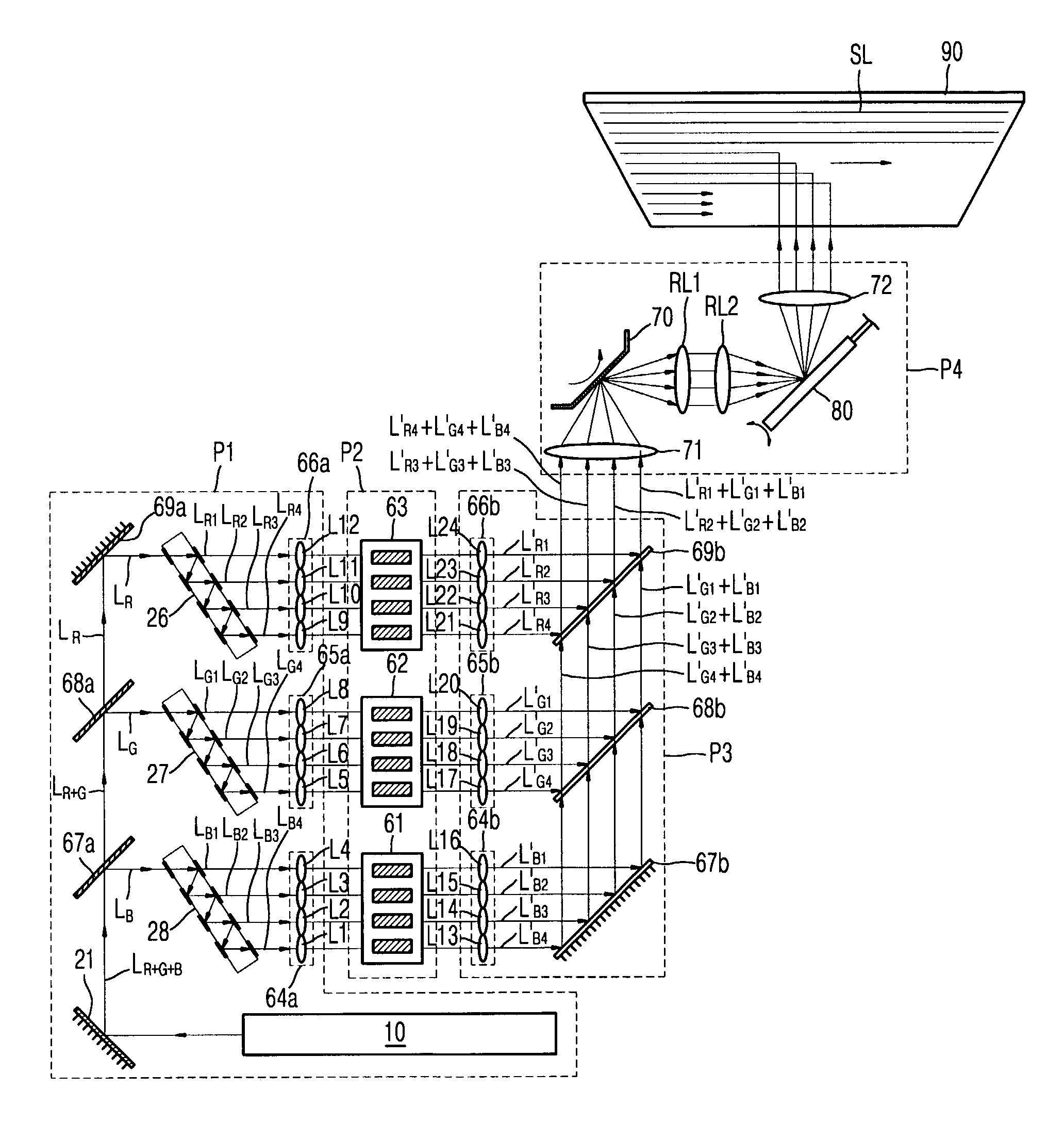
[0070]Referring to FIG. 9, the laser video projector according to the present invention includes a light generating portion P5, an optic modulator P2, an optic combining portion P6, an optic scanning portion P4, and a screen 90. The light generating portion P5 generates light to be used to project a video image, e.g., laser light. The optic modulator P2 modulates light generated by the light generating portion P5. The optic combining portion P6 combines light beams emitted from the optic modulator P2 via predetermined channels. The optic scanning portion P4 scans the combined light beams on the screen 90 to display a video image.

[0071]The light generating portion P5 includes first through fourth light sources LD1 through LD4 emitting red laser light, fifth through eighth light sources LD5 through LD8 emitting green laser light, and ninth through twelfth light sources LD9 through LD12 emitting blue laser light. The light generating portion P5 also includes twelve optical fibers OF1 t...

first embodiment

[0076]The optic combining portion P6 includes second micro focusing lenses FL2 corresponding on a one-to-one basis to twelve channels of the optic modulator P2 to focus modulate red, green, and blue laser light beams emitted from the channels of the optic modulator P2. The optic combining portion P6 also includes twelve optical fibers OF12 through OF24 to transmit modulated laser light beams emitted from the optic modulator P2 to the optic scanning portion P4. The thirteenth through sixteenth optical fibers OF13 through OF16 transmit modulated red laser light beams, the seventeenth through twentieth optical fibers OF17 through OF20 transmit modulated green laser light beams, and the twenty first through twenty fourth optical fibers OF21 through F024 transmit modulated blue laser light beams. The second micro focusing lenses FL2 are attached to respective ends of the thirteenth through twenty fourth optical fibers OF13 through OF24 which receive the modulated red, green, and blue las...


PUM

PropertyMeasurementUnit
reflectanceaaaaaaaaaa

Abstract

Provided are a laser video projector having a multi-channel acousto-optic modulator, and a method and circuit for driving the laser video projector. The laser video projector includes a light generating portion, an optic modulator, an optic combining portion, and an optic scanning portion. The light generating portion emits light to be used to project a video image. The optic modulator modulates the light incident from the light generating portion by using the video signal. The optic combining portion combines modulated light beams emitted from the optic modulator. The optic scanning portion scans light incident from the optic combining portion on a screen. The optic modulator has six or more optic modulation channels so that a plurality of red light beams, a plurality of green light beams, and a plurality of blue light beams incident in a state suitable for optic modulation are simultaneously modulated. Accordingly, limitations in the performance of an optic modulator and an optic scanner can be overcome. Also, a laser video projector can be made small. In addition, the degree of freedom for arranging components increases and the components can be well arranged. Furthermore, a video image of high brightness can be realized.

Description

BACKGROUND OF THE INVENTION[0001]This application claims the priority of Korean Patent Application No. 2002-13256, filed on Mar. 12, 2002, in the Korean Intellectual Property Office, the disclosure of which is incorporated herein in its entirety by reference.FIELD OF THE INVENTION[0002]The present invention relates to a laser video projector, and more particularly, to a laser video projector having a multi-channel acousto-optic modulator, and a method and circuit for driving the same.DESCRIPTION OF THE RELATED ART[0003]Lasers are used in various types of displays because of their optical characteristics, e.g., a monochromatic characteristic having a line spectrum almost close to zero, a straightforward characteristic, a condensing characteristic, high brightness, and the like.[0004]In a display, a laser can realize three times more natural colors than a fluorescent substance. Also, when compared with a lamp, the laser can greatly improve the optical conversion efficiency and reduce ...

Claims


Application Information

Patent Timeline
Patent Type & Authority Patents(United States)
IPC IPC(8): H04N5/74G02B26/10G02F1/11H04N9/31
CPCH04N9/3129H04N5/74
Inventor LEE, JIN-HODHO, SANG-WHOE
Owner SAMSUNG ELECTRONICS CO LTD
Why Eureka
Try Eureka