
High speed swept frequency spectroscopic system

a swept frequency and spectroscopic system technology, applied in the field of spectroscopy systems, can solve the problems of loss of coherence in light signal and difficulty in coupling light from test cell to fiber, and achieve the effect of reducing the loss of coupling ligh

Active Publication Date: 2007-02-27
WISCONSIN ALUMNI RES FOUND
View PDF2 Cites 18 Cited by
  • Summary
  • Abstract
  • Description
  • Claims
  • Application Information

AI Technical Summary

Benefits of technology

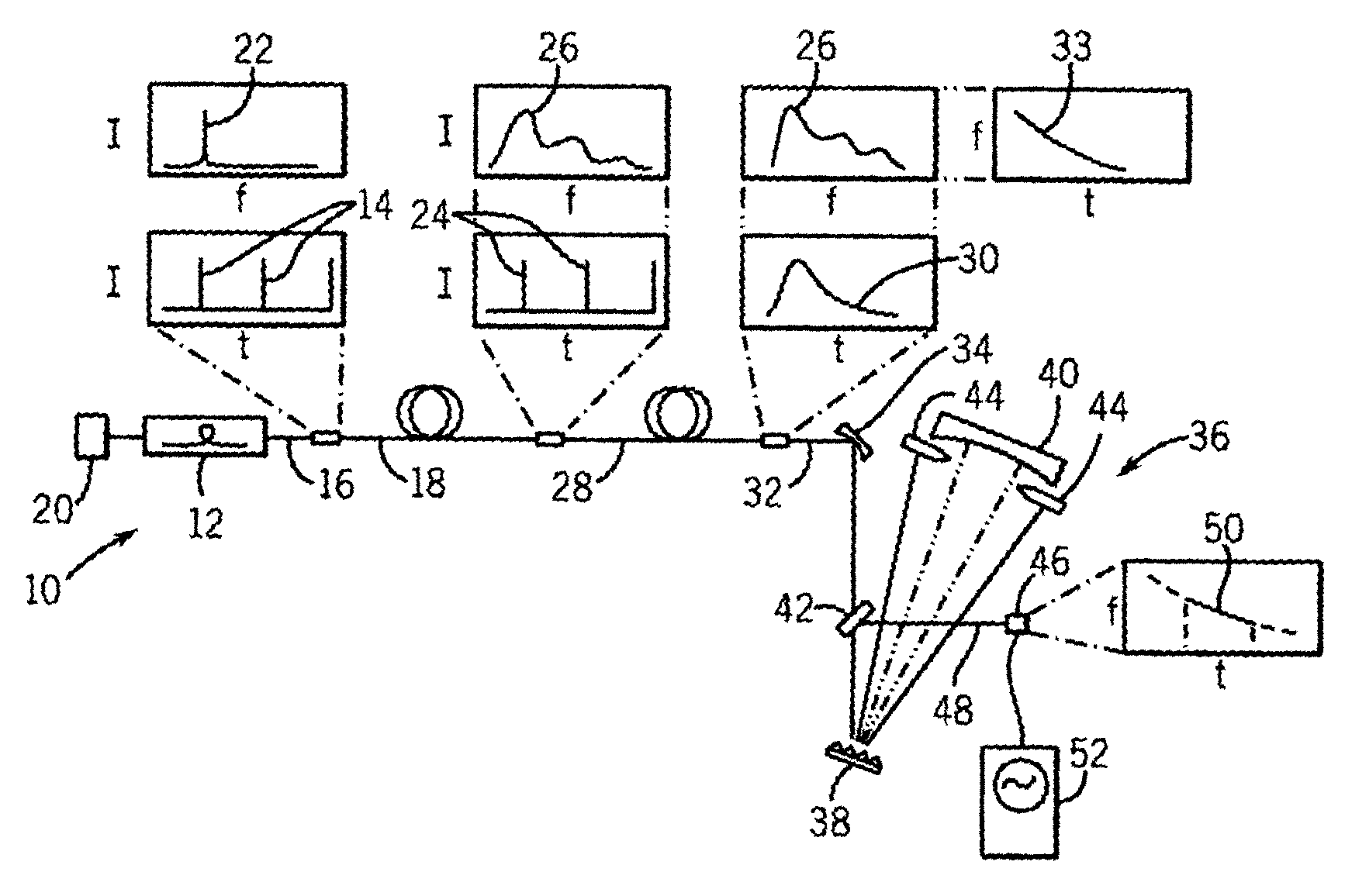
[0007]The present invention provides an improved spectroscopy system in which a short multi-frequency pulse is received directly by a fiber optic cable to spread the frequency in time prior to its being transmitted into a test cell. This approach significantly reduces the losses in coupling light to the optic fiber and avoids the measurement of unwanted nonlinear processes as might occur under simultaneous excitation of the test material with multiple frequencies of light.
[0008]In a preferred embodiment, the multifrequency light source is created by a laser pulse transmitted through a non-linear fiber to broaden its spectrum. The laser, non-linear fiber, and frequency spreading fiber may be easily joined with minimal coupling losses to produce a robust light source.

Problems solved by technology

The CCl4 chamber is cumbersome and causes a loss of coherence in the light signal from the laser.
Coupling the light from the test cell to the fiber is difficult.

Method used


Image

  • High speed swept frequency spectroscopic system
  • High speed swept frequency spectroscopic system
  • High speed swept frequency spectroscopic system

Examples


Embodiment Construction

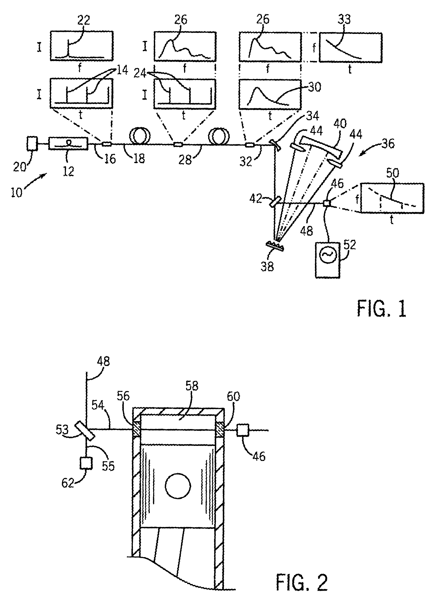
[0032]Referring now to FIG. 1, the agile laser 10 of the present invention employs a fiber laser 12 such as a passively mode-locked Er-doped fiber laser such as is sold by IMRA under the trade name Femtolite, commercially available from IMRA of Ann Arbor, Mich.

[0033]In the preferred embodiment, the fiber laser 12 is controlled by associated trigger electronics 20 to produce a three-hundred femtosecond pulse of 1.56-micrometer light at a repetition rate of forty-eight MHz. Each of these short pulses 14 has a narrow frequency bandwidth 22 (spectra), being substantially 0.02 micrometers in frequency width. The average power of the pulses 14 is sixty milliwatts with a peak power of five kilowatts.

[0034]The short pulses 14 are communicated through a fiber coupler 16 of the fiber laser 12 to a nonlinear fiber 18. The nonlinear fiber 18 may be two-hundred meters of PM-HN-DSF fiber available from Sumimoto Electric Industries of Osaka, Japan. Nonlinear processes such as self-phase modulation...


PUM


Abstract

A high scan rate spectroscopic system converts a narrow-band laser pulse into a multispectral pulse, using, for example, a nonlinear fiber. The multispectral pulse is then converted to a swept frequency pulse through a second fiber impressing a frequency-dependent delay in the light beam which is then applied to the object to be tested.

Description

CROSS REFERENCE TO RELATED APPLICATIONS[0001]This application is based on provisional application 60 / 402,492 filed Aug. 8, 2002 and entitled “High Speed Swept Frequency Spectroscopic System” and claims the benefit thereof.STATEMENT REGARDING FEDERALLY SPONSORED RESEARCH OR DEVELOPMENTBACKGROUND OF THE INVENTION[0002]The present invention relates to spectroscopy systems and in particular to a high-speed spectroscopy system suitable for analyzing highly dynamic systems.[0003]Spectroscopy studies the interaction between a material or materials and different frequencies of light to characterizes the spectral response of materials, such as gases, liquids, aerosols, solids, particulates, fiber-optic components etc. as may be related to physical properties of the material under test (e.g., temperature, pressure, velocity, composition, size, stress / strain. The interaction studied can be absorption, or reflectivity, scattering, fluorescence, etc.[0004]The material being studied by spectrosco...

Claims


Application Information

Patent Timeline
IPC IPC(8): G01J3/28G01J3/433
CPCG01J3/4338G01J3/2889
Inventor SANDERS, SCOTT T.
Owner WISCONSIN ALUMNI RES FOUND
Learn More