
Dynamic routing for a measurement system

a measurement system and dynamic routing technology, applied in the direction of program control, instruments, testing circuits, etc., can solve the problems of insufficient hardware resources, inconvenient routing determination process, and laborious and error-prone effor

Active Publication Date: 2007-02-27
NATIONAL INSTRUMENTS
View PDF24 Cites 20 Cited by
  • Summary
  • Abstract
  • Description
  • Claims
  • Application Information

AI Technical Summary

Benefits of technology

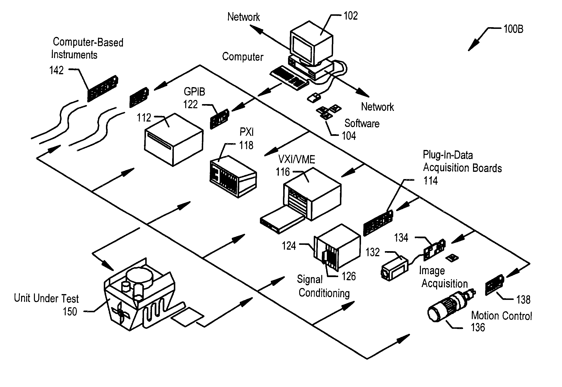
[0023]The method may programmatically determine the plurality of routes from the source terminal to the destination terminal and store the plurality of routes. The programmatically determined routes may then be usable to route signals in performing the measurement task. In one embodiment, each of the plurality of routes may traverse one or more public buses in the measurement system, such as trigger buses, including one or more of a RTSI bus, a PXI trigger backplane, and an external trigger bus, among others. To prevent resource conflicts on the one or more public buses, in one embodiment, one or more reservation protocols may be performed for the computed routes to prevent resource conflicts on the one or more public buses. In another embodiment, one or more routes may be computed to avoid the resource conflicts.

Problems solved by technology

Furthermore, when multiple devices are included in the measurement system, additional inter-device routing must be determined and specified, which may complicate the routing determination process substantially.
Therefore, a user may need to carefully analyze each prospective route to determine which is most suitable for the task, an effort which may be tedious and error prone.
However, prior art approaches generally do not facilitate the configuration of multiple signal modifiers between the source and destination, which may result in underutilization of hardware resources.
A traditional Application Programming Interface (API) would be limited to configuring only one of the inverters between the source and destination, resulting in underutilization of the hardware.
Additionally, traditional APIs do not account for the effect of multiple inverters on a signal.
Since traditional API's only evaluate a route's source and destination, they cannot program the components of the route with much flexibility.
Furthermore, routing across devices using a traditional API is generally only achievable by breaking up a multi-device route into two or more component routes.
In prior art systems, routes defined or managed at the level of source / destination terminal pairs cannot easily share hardware resources.
There are a number of drawbacks to this method of presentation.
This requires time and effort at the expense of documentation and software development tasks.
Additionally, because the table is built by hand, the table is prone to mistakes.
Second, when a device is modified or functionality is added, the routability table may need to be amended, which increases the likelihood for a number of errors.
Additionally, any pre-existing documentation will not be updated because once paper documentation is printed, it is not changeable.
Device families also present a problem for this approach, in that while devices in a family are normally exactly the same in most respects, they often differ slightly in terms of routability.
Thus, maintaining synchrony and consistency between the various routability tables may be problematic.

Method used


Image

  • Dynamic routing for a measurement system
  • Dynamic routing for a measurement system
  • Dynamic routing for a measurement system

Examples


Embodiment Construction

Incorporation by Reference

[0061]The following U.S. Patent Applications are hereby incorporated by reference as though fully and completely set forth herein:

[0062]U.S. application Ser. No. 10 / 008,792 titled “Measurement System Software Architecture for Easily Creating High-Performance Measurement Applications” filed Nov. 13, 2001, whose inventors were Geoffrey Schmit, Brent Schwan, Jonathan Brumley, Thomas A. Makowski and Christopher T. Bartz now abandoned;

[0063]U.S. Provisional Application Serial No. 60 / 301,785 titled “Measurement System Software Architecture for Easily Creating High-Performance Measurement Applications” filed Jun. 29, 2001, whose inventors were Geoffrey Schmit, Brent Schwan, Jonathan Brumley, Thomas A. Makowski and Christopher T. Bartz;

[0064]Pending U.S. application Ser. No. 10 / 010,826 titled “System of Measurements Experts and Method For Generating High-Performance Measurements Software Drivers” filed Nov. 13, 2001, whose inventors were Geoffrey Schmit, Jonathan B...


PUM


Abstract

System and method for performing dynamic routing in a measurement system to perform a measurement task. The system includes a computer and one or more measurement devices. One or more topography descriptions (TD) representing connectivity between devices and / or device components in the measurement system are received and preprocessed to generate corresponding graphs. A routing expert receives and analyzes a routing specification indicating source and destination terminals in the measurement system. The system dynamically computes a plurality of routes from the source terminal to the destination terminal by traversing the graphs and selecting the plurality of routes based on a metric. The computed routes are stored in a run-time specification for use at runtime to perform the measurement task. At runtime, a route is selected from the plurality of routes, and the system configures the one or more measurement devices with the selected route for performing the measurement task.

Description

CONTINUATION DATA[0001]This application is a Continuation of U.S. application Ser. No. 10 / 174,445 titled “Shared Routing In A Measurement System” filed Jun. 18, 2002, now abandoned, whose inventor was Robert W. Thurman.FIELD OF THE INVENTION[0002]The present invention relates to the field of measurement and automation systems, and more particularly to a system and method for performing dynamic routing for a specified task in a measurement system.DESCRIPTION OF THE RELATED ART[0003]Scientists and engineers often use measurement or automation systems to perform a variety of functions, including measurement of a physical phenomena or unit under test (UUT), test and analysis of physical phenomena, simulation, hardware-in-the-loop testing, process monitoring and control, control of mechanical or electrical machinery, data logging, laboratory research, and analytical chemistry, to name a few examples.[0004]A typical measurement system comprises a computer system with a measurement device ...

Claims


Application Information

Patent Timeline
Patent Type & Authority Patents(United States)
IPC IPC(8): G01M19/00G06F19/00G01M99/00G06F9/44G06F15/173G06F17/00G06F17/50G09G5/00
CPCG06F8/71G05B2219/23258G05B2219/2656G05B2219/23291G06F15/173
Inventor CARBONELL, JEFF A.THURMAN, ROBERT W.
Owner NATIONAL INSTRUMENTS
Learn More