
Method and device for removing part of concrete structure

a concrete and part technology, applied in the direction of disloding machines, building repairs, ways, etc., can solve the problems of demolishing noise, unnecessarily or accidentally breaking the base concrete beneath the reinforced concrete, and the method is defective and almost unpractical

Inactive Publication Date: 2007-03-06
ASAKURA KENSUKE
View PDF7 Cites 1 Cited by
  • Summary
  • Abstract
  • Description
  • Claims
  • Application Information

AI Technical Summary

Benefits of technology

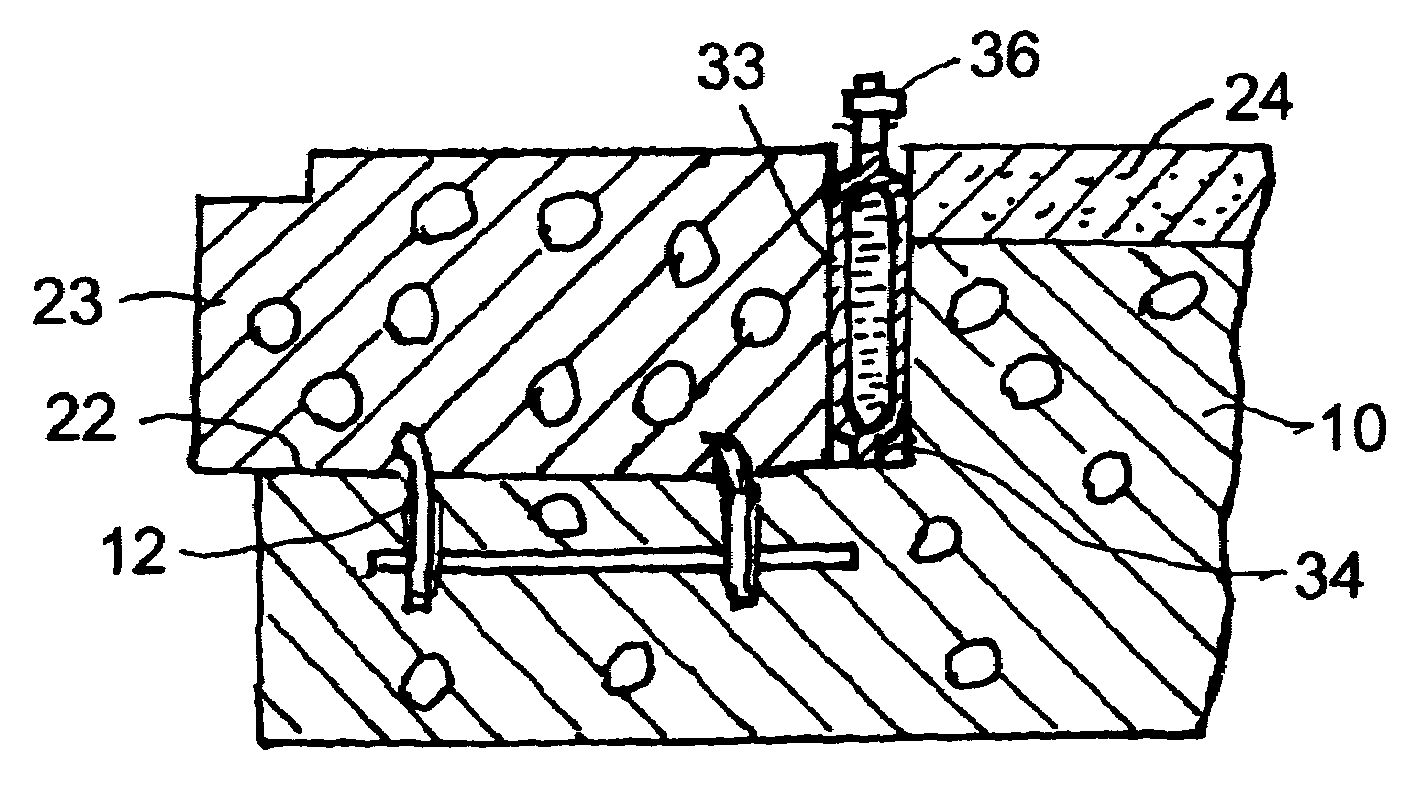
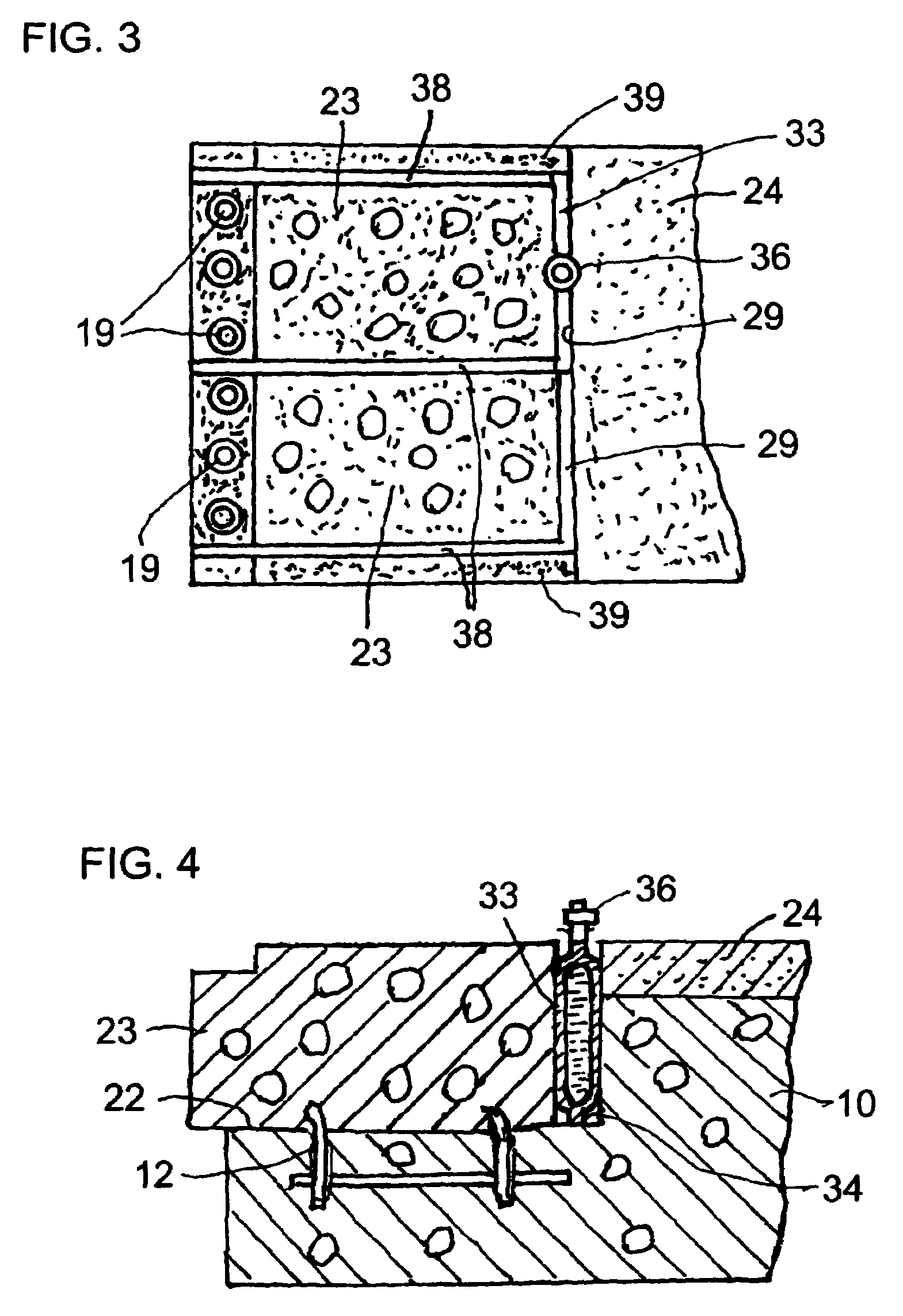
[0006]The present invention also refers to a flat jack that comprises two metallic plates joined to each other with a circumferential joint portion formed along the whole periphery of the metallic plates, and an inlet (36) for introducing into the jack (33) pressurized fluidic material such as water, oil, gel or vaseline except gas to inflate the jack (33) that thereby produces a great expansive force.

Problems solved by technology

However, this method is defective and almost unpractical in that it involves demolishing noise when the reinforced concrete is broken and crushed by drills or breakers operated for long hours.
Also, in some cases, a base concrete beneath the reinforced concrete may unnecessarily or accidentally be broken by excessive crushing operation of breakers, requiring an additional work to repair the broken base concrete.
However, cutters of this kind have not been used in removing a reinforced concrete for fixing expansion joints

Method used


Image

  • Method and device for removing part of concrete structure
  • Method and device for removing part of concrete structure
  • Method and device for removing part of concrete structure

Examples


Embodiment Construction

[0012]An embodiment of the present invention is described hereinafter in connection with the drawings.

[0013]The embodiment of the present invention shown in the drawings is applied to a technique for removing a reinforced concrete that mounts an expansion joint on a base concrete of a bridge.

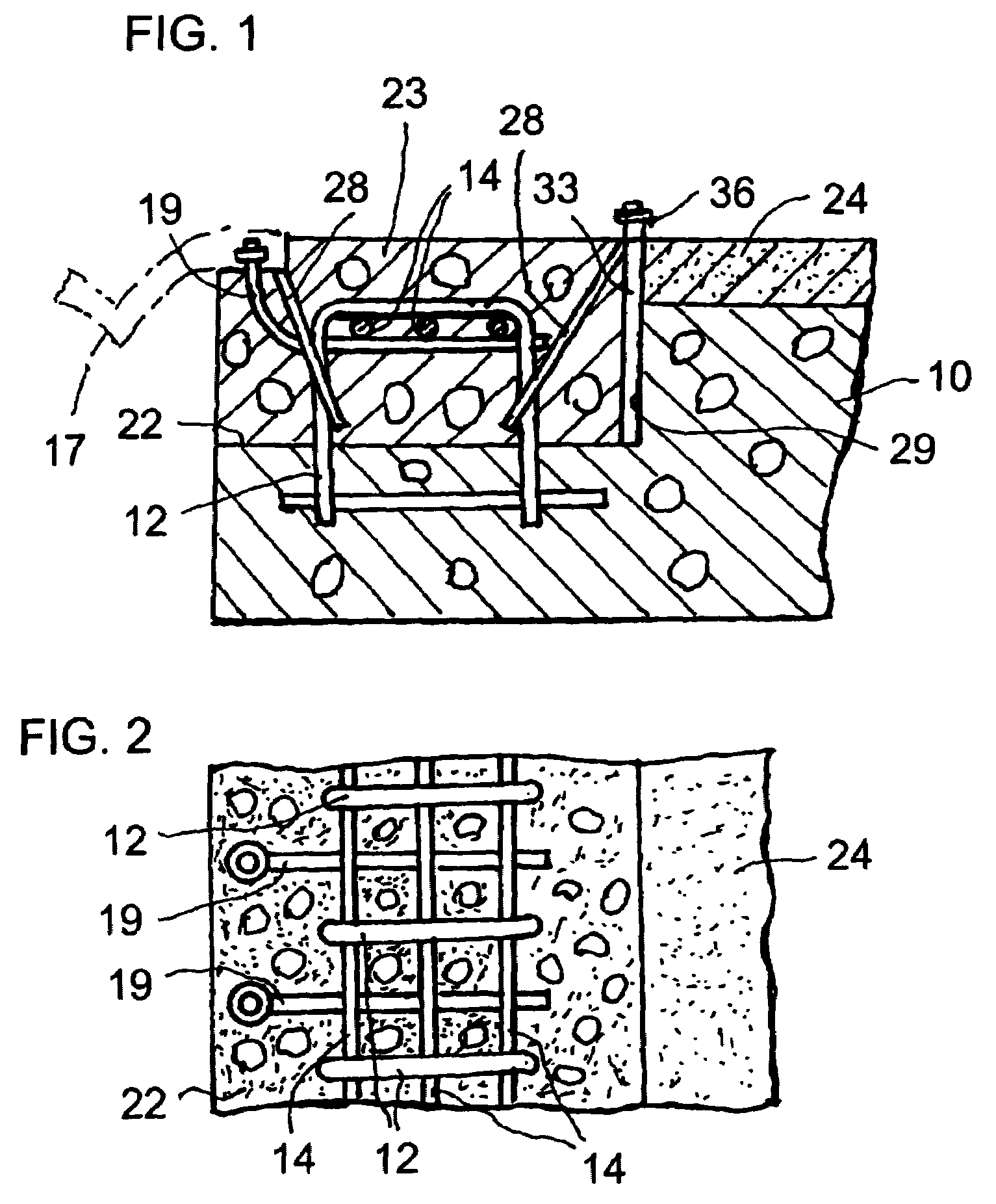
[0014]In FIGS. 1 and 2, a reference numeral “10” denotes an irremovable roadway slab or base concrete of a concrete construction, “12” symbolizes a plurality of reinforcing iron rods or rebars of generally inverted U-shape embedded in base concrete 10 and arrayed in a transverse direction at given intervals. Each of rebars 12 has a horizontal connecting portion and two vertical arms extending from both ends of the connecting portion into base concrete 10. A plurality of additional rebars 14 are attached at right angles to a bottom side of the horizontal connecting portion. As shown in the drawings, anchor bolts 19 for an expansion joint 17 are secured to rebars 14. A boundary plane 22 is formed ...


PUM


Abstract

This invention refers to a method for removing a part of concrete construction that comprises a base concrete; a reinforced concrete formed on the base concrete; rebars embedded in the base concrete and upwardly extending through the reinforced concrete; the method comprising the steps of: forming a slit in the reinforced concrete and disconnections at an intermediate of the rebars; applying an expansion force on opposite surfaces of the slit in the reinforced concrete to simultaneously break a boundary plane of the reinforced concrete; and removing the moved portion of the reinforced concrete from the base concrete as a scrap. Also, the present invention provides a flat jack suitable to break boundary planes of the scrap wherein the flat jack comprises two metallic plates joined to each other, and an inlet for introducing into the jack pressurized fluidic material to inflate the jack in order to produce a great expansive force.

Description

TECHNICAL FIELD[0001]This invention relates to a method and an apparatus for removing a part of a concrete construction. Specifically, bridges built for elevated highways are provided with roadway expansion joints mounted on the bridges, and the expansion joints are exchanged with new ones after elapse of some service life in a manner of removing the expansion joints and adjoining reinforced concretes for surrounding the expansion joints from slabs of the highways. The present invention provides a method and an apparatus suitable to remove such reinforced concretes.BACKGROUND OF THE INVENTION[0002]As shown in Japanese Patent Disclosure No. 57-77759, the inventor proposed a method and an apparatus for exchanging an expansion joint used for long period of time by providing each iron bar with a tensely weakened portion and embedding the iron bars and elongated inflatable flat vessels of metallic material in a reinforced concrete for fixing an expansion joint. In exchange, pressurized l...

Claims


Application Information

Patent Timeline
Patent Type & Authority Patents(United States)
IPC IPC(8): E01C11/04E04G23/08E01D19/06E01D22/00
CPCE01D19/06E04G23/08E01D22/00
Inventor ASAKURA, KENSUKE
Owner ASAKURA KENSUKE
Learn More