
Monitoring unit for monitoring the condition of a semi-permeable membrane

a semi-permeable membrane and monitoring unit technology, applied in gravity filters, feed/discharge of settling tanks, loose filtering material filters, etc., can solve the problems of affecting the operation efficiency of the system, the lack of methodology by which fouling or biofouling of the membrane is detected and monitored, and the semi-permeable membrane is severe. , to achieve the effect of improving the operating efficiency of the system

Inactive Publication Date: 2007-03-06
SASOL TEKHNOLODZHI PROPRIEHJTEHRI LTD
View PDF16 Cites 18 Cited by
  • Summary
  • Abstract
  • Description
  • Claims
  • Application Information

AI Technical Summary

Benefits of technology

[0008]It is accordingly an object of the present invention to provide a novel apparatus for monitoring the condition of a semi-permeable membrane, especially of the type utilized in a reverse osmosis water purification system, that will overcome or at least minimize some of the disadvantages associated with known apparatus of this kind.
[0023]The monitoring unit also may include an outlet manifold located intermediate the flow chamber and the feed fluid outlet. The outlet manifold may be arranged such that it prevents areas of decreased flow in the flow chamber, so as to prevent preferential foulant adsorption or biological growth. The manifolds also may be arranged so as to permit reverse flow through the monitoring unit for evaluating the effectiveness of back flushing on removal of impurities adsorbed onto the membranes.
[0033]According to yet a further aspect of the invention there is provided the use of a monitoring unit including a semi-permeable test membrane for evaluating one or more of the following operating parameters in a water purification system namely the efficiency of different types of chemicals utilized in the system, such as anti-scalants, biocides and anti-fouling chemicals; the effect of using different membranes and / or associated spacer means in the water purification system on the operating efficiency of the system; and efficiency of different membrane cleaning methods.
[0034]According to yet another aspect of the invention there is provided the use of a monitoring unit according to the invention for evaluating one or more of the following parameters in a spiral membrane reverse osmosis water purification system namely fouling of the spiral membrane; the efficiency of different types of chemicals utilized in the system, such as anti-scalants, biocides and anti-fouling chemicals; the effect of using different membranes and / or associated spacer means in the water purification system on the operating efficiency of the system; and efficiency of different membrane cleaning methods.

Problems solved by technology

Moreover, uncontrolled microbiological growth in a feed fluid tank, pipelines or on the membranes themselves can result in severe biofouling of the semi-permeable membrane.
However, a major problem associated with this type of technology is the lack of methodology by which fouling or biofouling of the membrane is detected and monitored.
If the membrane is not cleaned in time, the membrane can be damaged permanently, unavoidably resulting in downtime of the system, associated production losses, and expensive maintenance and replacement costs for replacing the membrane.
One disadvantage associated with these types of apparatus is that relatively complicated valve and pressure sensor arrangements are required to effect proper working of the apparatus.
Another disadvantage is that the apparatus generally comprises a number of separate components that not only increases manufacturing, installation and maintenance costs, but also requires relatively skilled personnel for operating the apparatus.
Furthermore, it has been found that existing apparatus are often not sensitive enough for detecting fouling of the membrane in time, the situation being such that by the time fouling is eventually detected, the membrane is already damaged.

Method used


Image

  • Monitoring unit for monitoring the condition of a semi-permeable membrane
  • Monitoring unit for monitoring the condition of a semi-permeable membrane
  • Monitoring unit for monitoring the condition of a semi-permeable membrane

Examples


Embodiment Construction

[0037]Without limiting the scope thereof, one embodiment of the invention will now be described by way of example only and with reference to the accompanying drawings wherein

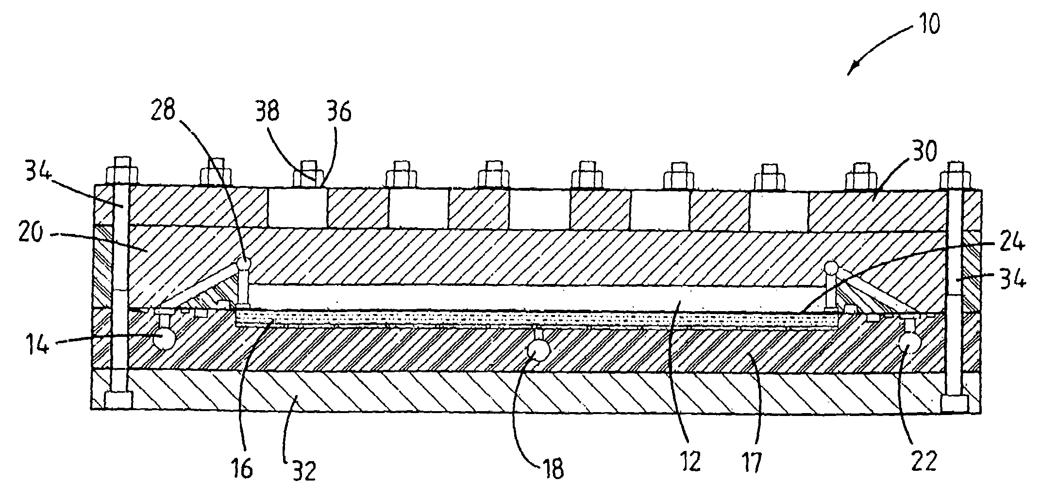
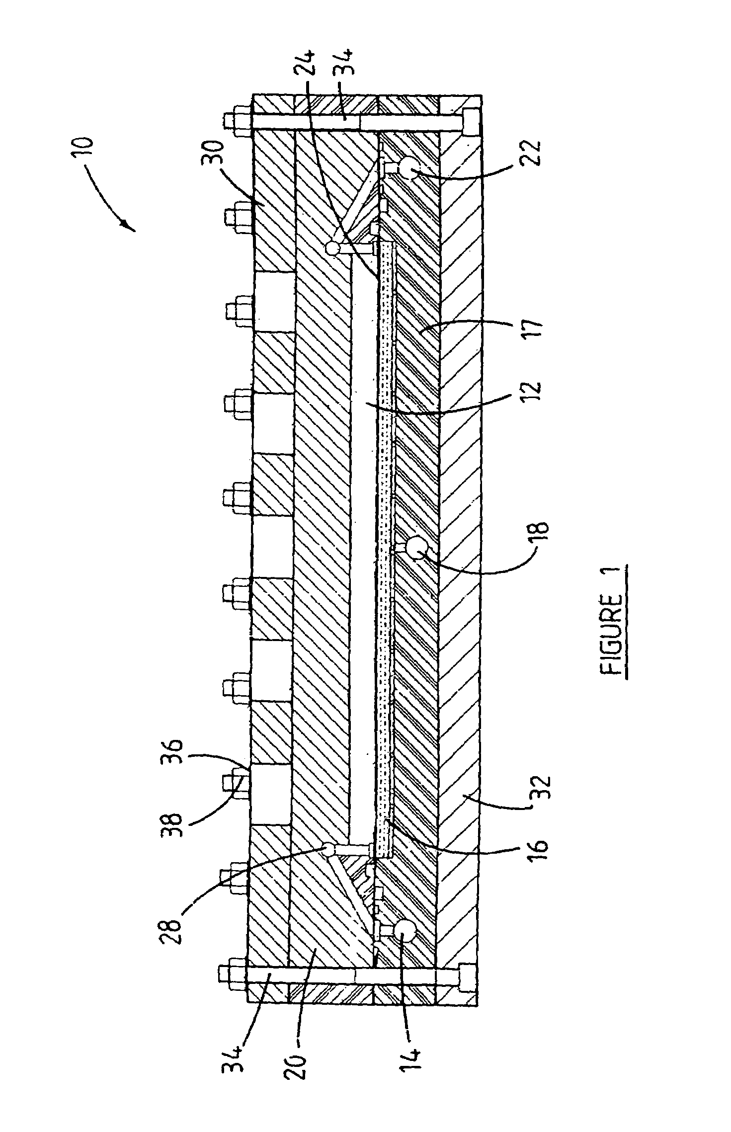
[0038]FIG. 1 is a cross-sectional side view of a monitoring unit according to one embodiment of the invention;

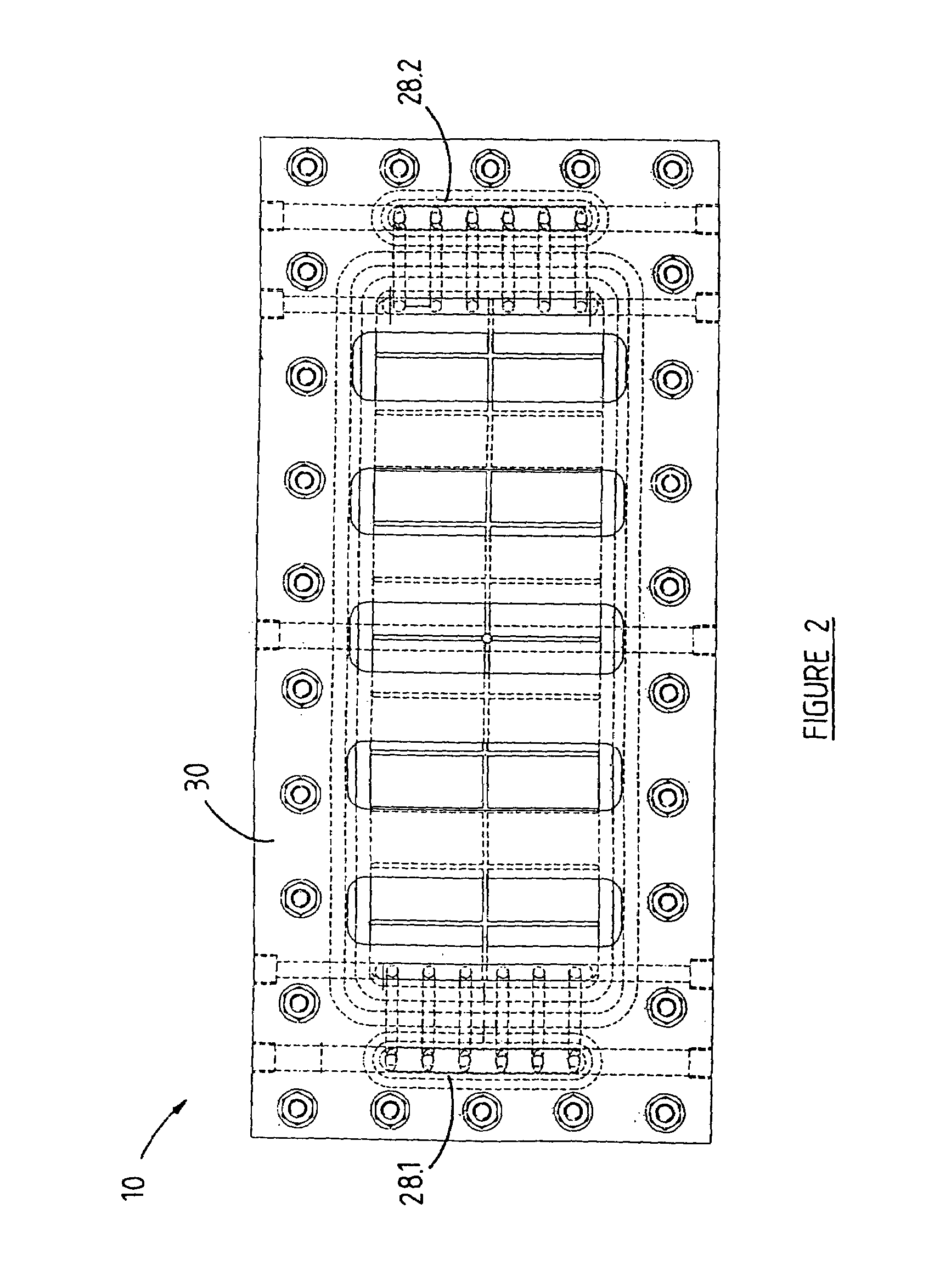
[0039]FIG. 2 is a plan view of the monitoring unit of FIG. 1; and

[0040]FIG. 3 is a perspective view of the monitoring unit of FIGS. 1 and 2.

[0041]A monitoring unit according to the invention is generally designated by reference numeral 10. The monitoring unit 10 is adapted for use in a water purification system that includes at least one water-cleaning unit wherein the water-cleaning unit comprises at least one membrane for cleaning water through reverse osmosis. Particularly, the monitoring unit 10 is adapted for monitoring the condition of a semi-permeable spiral membrane in a spiral membrane reverse osmosis water purification system by monitoring fouling of a semi-permeable test membrane 24 in the mon...


PUM

PropertyMeasurementUnit
pore sizesaaaaaaaaaa
pressureaaaaaaaaaa

Abstract

The invention concerns a monitoring unit [10] for monitoring the condition of a semi-permeable membrane [24] in a water purification system, and particularly the condition of spiral membrane in a reverse osmosis water purification system. The monitoring unit [10] comprises a flow chamber [12] that includes an inlet for permitting ingress of a feed fluid into the flow chamber [12], and a feed fluid outlet [22] for permitting at least partial through-flow of the feed fluid through the flow chamber [12] such that cross-flow conditions apply in the flow chamber [12]. The semi-permeable membrane [24] is at least partly supported in the flow chamber [12]. The monitoring unit [10] further comprises at least one fluid outlet [18] arranged in fluid communication with the flow chamber [12] for permitting egress of fluid from the monitoring unit [10] after having passed through the membrane [24]; and an inspection window [20] for permitting visual inspection of the semi-permeable membrane [24]. The invention also extends to the use of such a monitoring unit [10] in evaluating various operating parameters of such a system, and to a water purification system including such a monitoring unit [10] or test cell.

Description

INTRODUCTION [0001]This invention relates to an apparatus for monitoring performance of a water purification system. Particularly, the invention relates to a monitoring unit or test cell for monitoring fouling and biofouling of semi-permeable reverse osmosis membranes utilized in water purification systems. The invention also extends to the use of such a monitoring unit in evaluating various operating parameters of such a system, and to a water purification system including such a monitoring unit or test cell.BACKGROUND OF THE INVENTION [0002]Those who are familiar with the industry will appreciate that a reverse osmosis water purification system provides for cleaning an impure aqueous solution by forcing the solution through a semi-permeable membrane to obtain a substantially pure aqueous solution. More particularly, an impure aqueous solution is generally pumped, under pressure, through the semi-permeable membrane, which is designed for retaining impurities such as organic and ino...

Claims


Application Information

Patent Timeline
Patent Type & Authority Patents(United States)
IPC IPC(8): B01D35/00B01D63/00B01D35/14B01D61/12B01D65/10
CPCB01D65/102B01D61/12
Inventor MAARTENS, ANDREJACOBZ, EDMUND PETRUSPEET, DOUGLASAUGUSTYN, PETRONELLA MARIA
Owner SASOL TEKHNOLODZHI PROPRIEHJTEHRI LTD
Learn More