
Absorption power measuring device

a technology of absorption power and measuring device, which is applied in the direction of instruments, diagnostic recording/measuring, suspensions, etc., can solve the problems of inconvenient handling of absorption power, aging effect of electromagnetic characteristics, and presented inconvenient handling and transportation

Inactive Publication Date: 2007-03-06
GOOGLE LLC
View PDF9 Cites 20 Cited by
  • Summary
  • Abstract
  • Description
  • Claims
  • Application Information

AI Technical Summary

Benefits of technology

The present invention relates to an apparatus for measuring absorbed power in a human body. The apparatus includes an electromagnetic field probe that is inserted inside a phantom which simulates a part of the human body. The field strength of a radio wave that is externally irradiated upon the phantom is measured, and the power of the radio wave that is absorbed by the human body is estimated based on the measured values. The phantom has a volume that is equal to 5×105 mm3 or less. The invention also provides a scan mechanism that performs a relative movement between the phantom and the radio transmitter. The technical effects of the invention include improved accuracy in measuring absorbed power and reduced size of the phantom.

Problems solved by technology

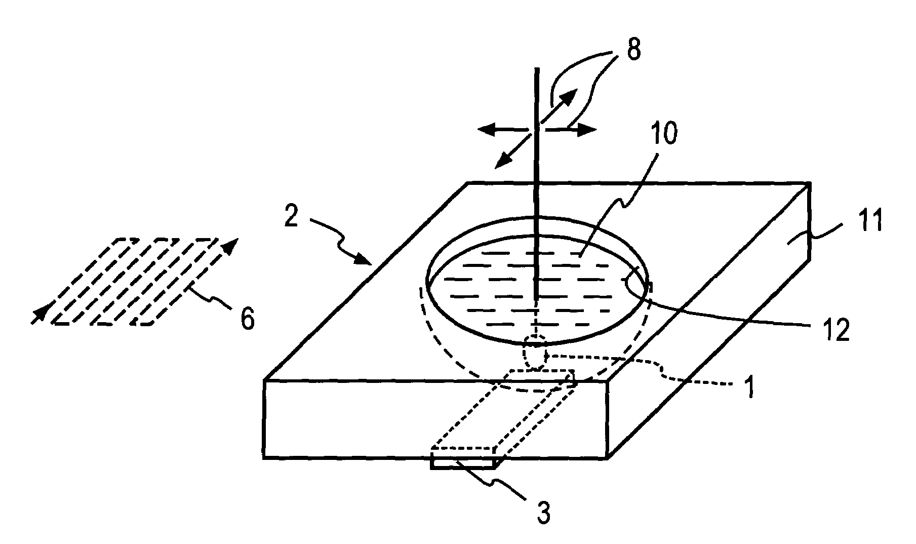
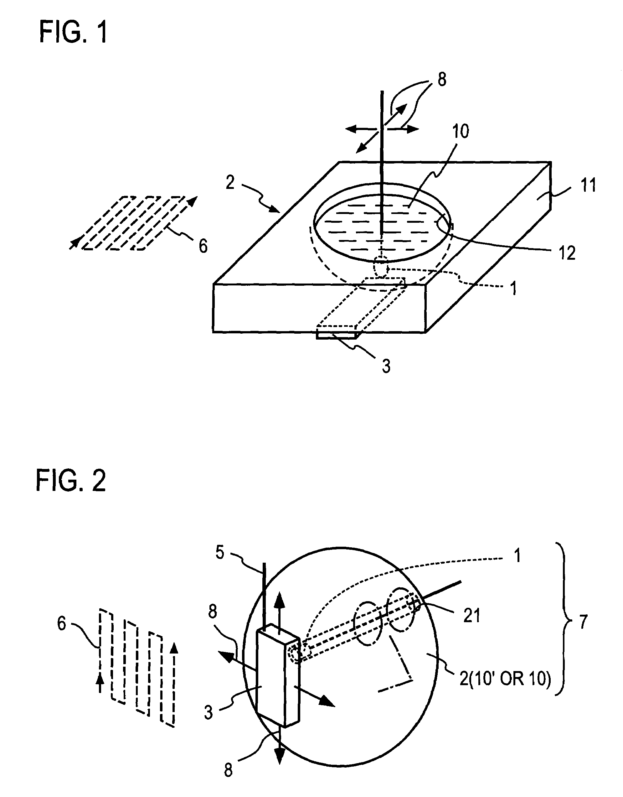
The head simulation phantom 2 shown in FIG. 1 is filled with the liquid medium 10, and is inconvenient in its handling.
Since the probe 1 is moved within the liquid medium 10 for purpose of scan and measurement, the liquid medium 10 remains open to the air, and there arises a problem that the liquid medium 10 may be evaporated to cause an aging effect of the electromagnetic characteristics thereof.
Thus, a conventional head simulation phantom 2 has a weight which is as high as 4200 g or 8400 g, and presented an inconvenience in its handling and transportation.
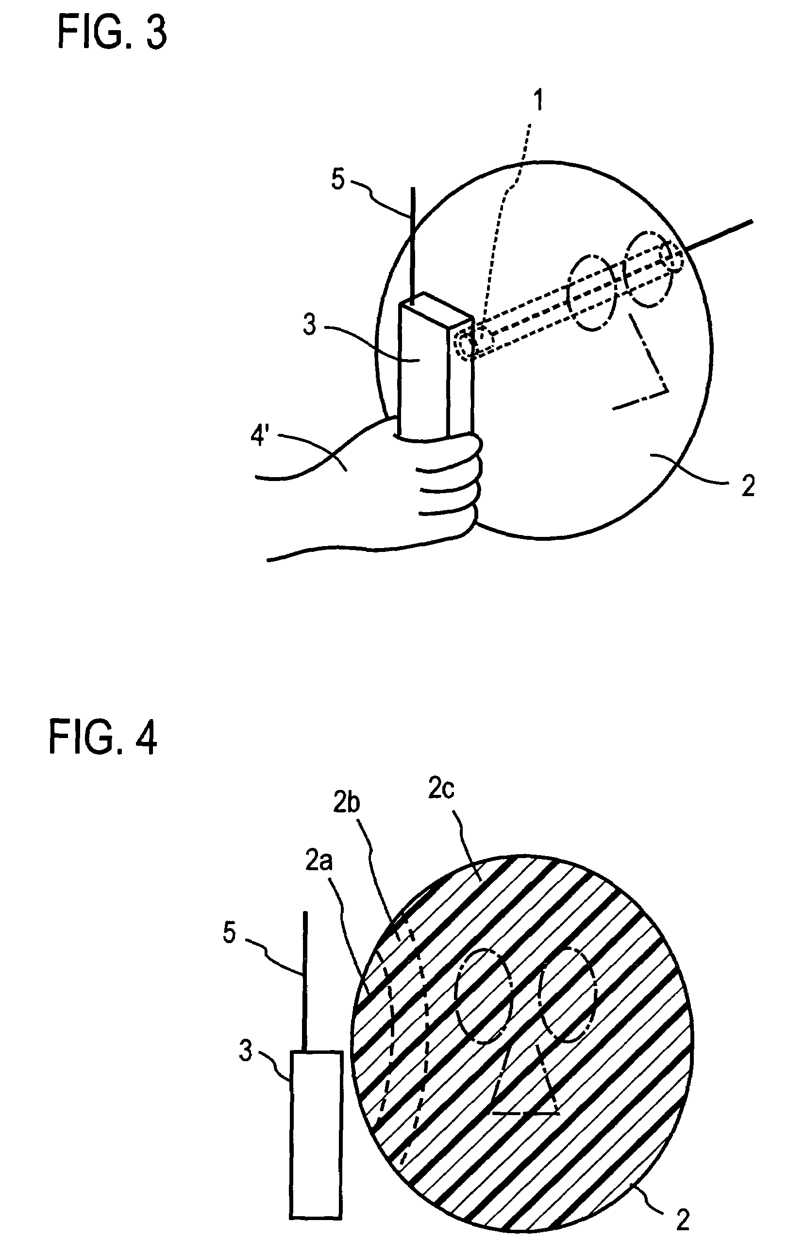
Where the radio transmitter has a bulky volume or heavy, it may be difficult to conduct a spatial scan of the radio transmitter 3 relative to the phantom 2 by hand 4′.

Method used


Image

  • Absorption power measuring device
  • Absorption power measuring device
  • Absorption power measuring device

Examples


Embodiment Construction

First Invention

[0055]The principle of one aspect of the present invention will be described first. When the head simulation phantom 2 which simulates the configuration and the electromagnetic characteristics of the head of the human body shown in FIG. 2 is irradiated with a radio wave in SHF band, which represents a transmission frequency of a mobile telephone, or with a radio wave of a higher frequency band, the absorption of the power by the phantom 2 takes place in a manner indicated in FIG. 4. As shown, the absorption will be greater in a surface layer 2a of the head simulation phantom 2 which is located close to the radio transmitter 3, but will be reduced in the inner thin layer 2b, and will be substantially equal to zero in the inside 2c. Specifically, when a half-wavelength dipole antenna is disposed at a distance of 10 mm with respect to the phantom 2 having a diameter of 200 mm, for example, and a radio wave (of frequency 900 MHz) is irradiated upon the phantom 2, it follo...


PUM

PropertyMeasurementUnit
thicknessaaaaaaaaaa
volumeaaaaaaaaaa
dielectric loss tan δaaaaaaaaaa

Abstract

In an apparatus for measuring absorbed power including an electromagnetic field probe 1 fixedly mounted within a head simulation phantom 2 which simulates the configuration and the electromagnetic characteristics of a head of a human body, and wherein the strength of an electric field or a magnetic field of a radio wave externally irradiated upon the head simulation phantom 2 is measured by the electromagnetic field probe 1, and the power of the radio wave absorbed by the head is estimated on the basis of measured values, the head simulation phantom 2 comprises a solid dielectric 10′ which simulates the configuration and the electromagnetic characteristics of a head of a human body or a liquid dielectric 10 which simulates the electromagnetic characteristics of a head of a human body and which is filled in an enclosed vessel 10 which simulates the configuration of a head of a human body. The volume of the solid dielectric 10′ or the volume of the enclosed vessel 11 is equal to or less than 5×105 mm3.

Description

TECHNICAL FIELD[0001]The present invention relates to an apparatus which uses a phantom simulating the electromagnetic characteristics of a human body to measure the amount of absorption by the human body of a radio wave or waves radiated from a radio transmitter which is operated in the vicinity of the body through a relative scan of the phantom and the radio transmitter.BACKGROUND ART[0002]In the prior art practice, the power absorbed by a human body, for example, by the head of the human body, has been estimated by constructing a head simulation phantom which simulates the configuration and the electromagnetic characteristics of the head of the human body and measuring the amount of power absorbed by the phantom.[0003]A conventional example of the prior art will be described with reference to FIG. 1. A head simulation phantom 2 is constructed by forming a recess 12 configured to divide the head of the human body into two equal parts laterally in a top surface of a vessel 11 and f...

Claims


Application Information

Patent Timeline
Patent Type & Authority Patents(United States)
IPC IPC(8): C12Q1/68G01N15/06G01N25/18G01N33/00G01N33/48G01N22/00G01R29/08
CPCG01R29/08
Inventor IYAMA, TAKAHIROTARUSAWA, YOSHIAKIUEBAYASHI, SHINJINOJIMA, TOSHIO
Owner GOOGLE LLC
Learn More