Arc detection method utilizing a dynamic processing module

a dynamic processing module and arc detection technology, applied in short-circuit testing, emergency protective arrangements for limiting excess voltage/current, instruments, etc., can solve the problems of power failure, equipment destruction, and high frequency noise monitoring methods that do not allow monitoring systems, and achieve the effect of reducing or eliminating false alarms during arc monitoring by the eams, and reducing or eliminating waveform artifacts

Active Publication Date: 2007-03-06
HENDRY MECHANICAL WORKS
View PDF9 Cites 3 Cited by
  • Summary
  • Abstract
  • Description
  • Claims
  • Application Information

AI Technical Summary

Benefits of technology

[0010]The present invention seeks to provide methods and apparatuses that can be used in conjunction with a causal / non-causal Electric Arc Monitoring System (EAMS), to help reduce or eliminate waveform artifacts that can result from a monitored signal with decaying or increasing amplitude. By reducing or eliminating these artifacts, false alarms during arc monitoring by the EAMS can also be reduced or eliminated.

Problems solved by technology

Any electrical power system can be troubled by undesired electrical arcing, which can cause power failure, equipment destruction, and which in severe cases can even lead to fire or explosion.
The problems of electrical arcing are particularly critical in aircraft, ships, around flammable fluids or in other environments in which human life depends on proper electrical functions.
High frequency noise monitoring methods do not allow the monitoring system to respond to frequency components of the arc signature, which may lie in the general frequency range of the AC fundamental.
Such methods do not adequately detect more chaotic arc signatures, and they are plagued by false alarms related to transient load conditions, which are often well correlated to line frequencies.

Method used


Image

  • Arc detection method utilizing a dynamic processing module
  • Arc detection method utilizing a dynamic processing module
  • Arc detection method utilizing a dynamic processing module

Examples


Embodiment Construction

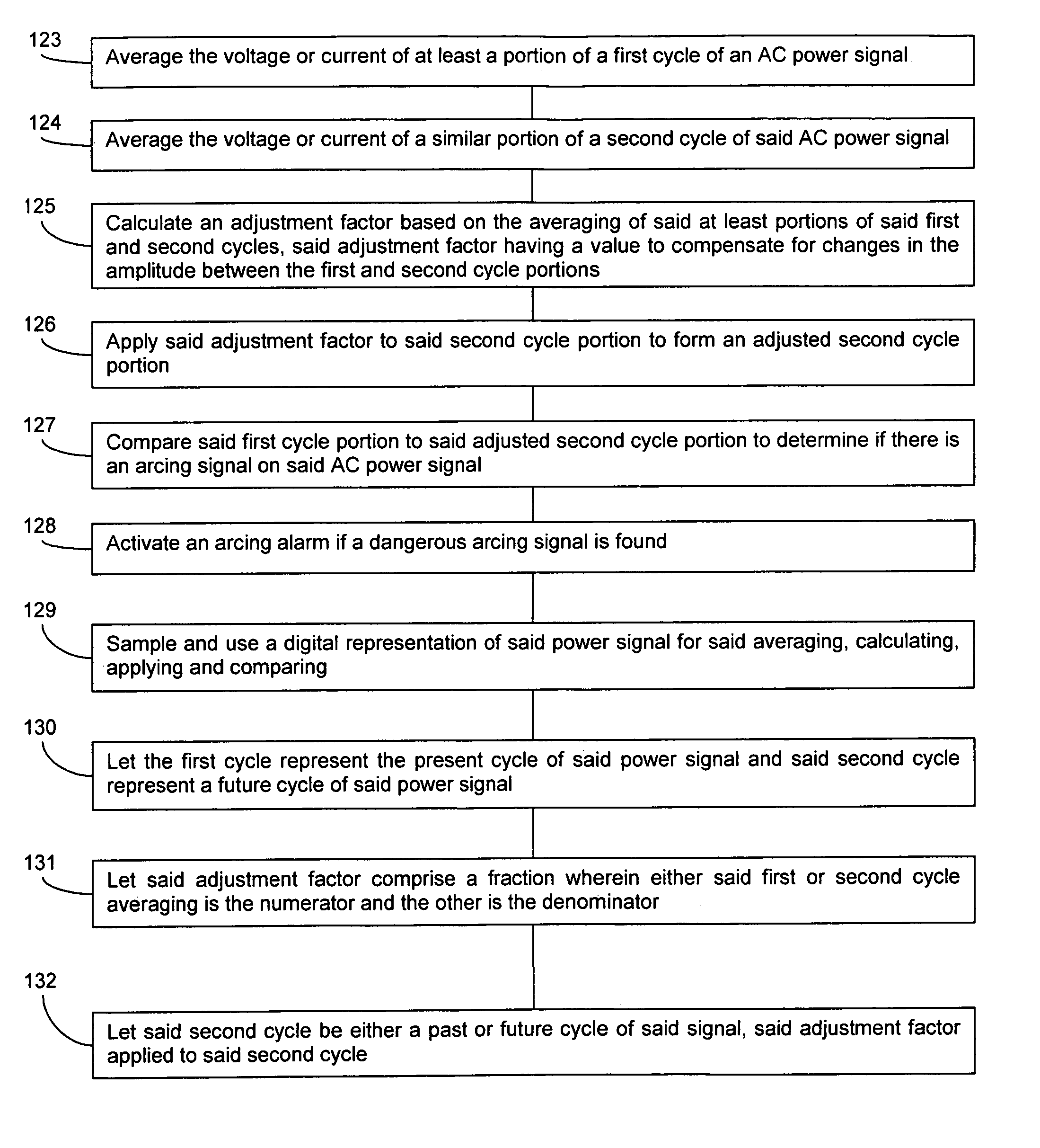
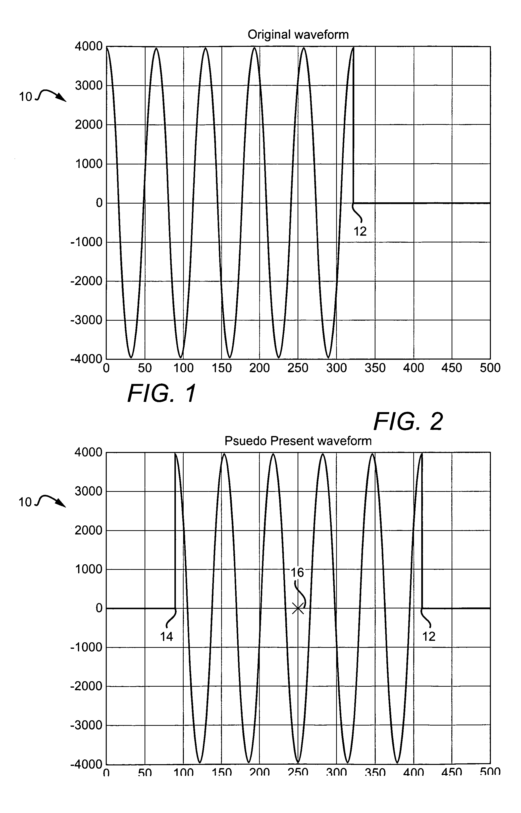
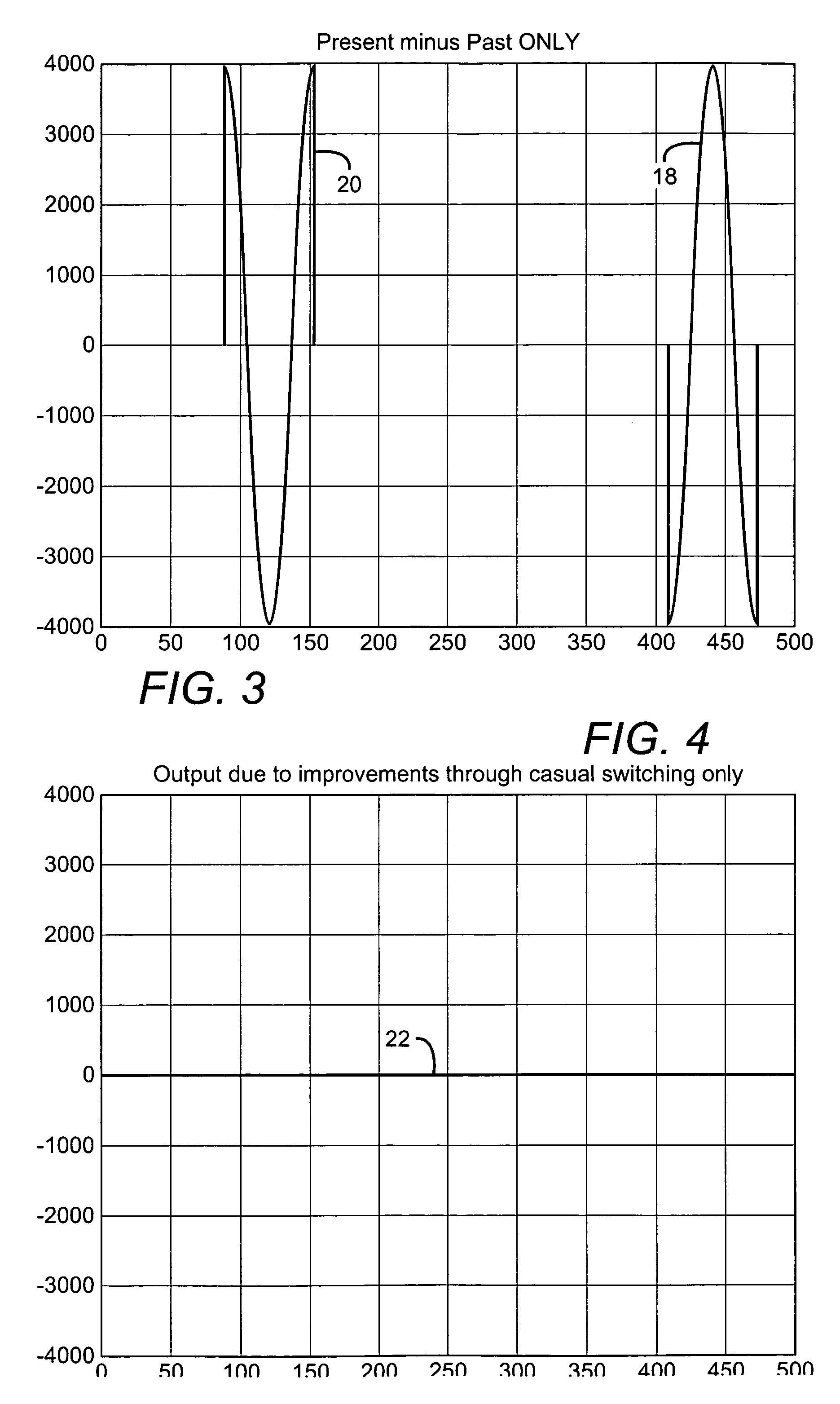
[0047]The present application can be used in many different arc detection systems but is particularly applicable to causal or causal / non-causal type arc detection systems used in alternating current (AC) power systems. One of these systems is described in U.S. Patent Application Publication US 2003 / 0227290 A1, to Parker and assigned to the same assignee as the present application. The publication is incorporated by reference as though fully set forth herein. These systems can subtract a particular signal cycle from a cycle immediately before or after such that after the subtraction that remains can be the chaotic artifact arc signal. If the arc signal has a high enough amplitude, an arcing alarm can be sounded indicating an arcing condition.

[0048]In one embodiment of a causal / non-causal system according to the present invention assigns a past, present and future portion of the monitored waveform. The invention then compares the present value of the waveform both with (a) the past va...


PUM


Abstract

Methods and systems for reliable arc detecting in systems having power signals that experience decay or increase in amplitude. One embodiment of a system for detecting electrical arcs by monitoring an alternating current power supply comprises a sampling circuit which samples electrical signals. It further comprises a delay circuit which receives the sampling circuit output and stores a time history of the output over an interval including a past, present and future versions of the history. Causal / non-causal logic compares the present version with the past and future versions to determine which will be used as an arc monitoring version to compare the present version to for arc monitoring. A dynamic processing module compensates for any amplitude differences between the present version and the arc monitoring version. An arc monitoring circuit analyzes the present version and adjusted arc monitoring version to determine if an arc signal is present.

Description

[0001]This application claims the benefit of provisional application Ser. No. 60 / 462,250 to Parker, which was filed on Apr. 11, 2003.BACKGROUND OF THE INVENTION[0002]1. Field of the Invention[0003]This invention relates to arc detection in alternating current (AC) power systems.[0004]2. Description of the Related Art[0005]Electrical power systems often distribute power as an alternating current (AC) waveform, both for historical and engineering reasons. Although the standard 60 Hz frequency is commonly used by power utilities, other frequencies such as 400 Hz are also used, for example, in civilian and military aircraft.[0006]Any electrical power system can be troubled by undesired electrical arcing, which can cause power failure, equipment destruction, and which in severe cases can even lead to fire or explosion. The problems of electrical arcing are particularly critical in aircraft, ships, around flammable fluids or in other environments in which human life depends on proper elec...

Claims


Application Information

Patent Timeline
IPC IPC(8): G01R31/08H01H9/50G01R31/02G01R31/12H02H1/00
CPCG01R31/021G01R31/1272G01R31/025H02H1/0015G01R31/58G01R31/52
Inventor PARKER, MICHAEL T.
Owner HENDRY MECHANICAL WORKS
Why Eureka
Try Eureka