Anti-cross conduction drive control circuit and method

a technology of control circuit and control circuit, applied in logic circuit coupling/interface arrangement, pulse generator, pulse technique, etc., can solve problems such as excessive current consumption and damage to power devices, and achieve the effect of avoiding cross-conduction and preventing the occurrence of race conditions

Active Publication Date: 2007-03-06
ANALOG DEVICES INC
View PDF11 Cites 30 Cited by
  • Summary
  • Abstract
  • Description
  • Claims
  • Application Information

AI Technical Summary

Benefits of technology

[0009]An anti-cross conduction driver control circuit and method are presented which overcome the problems noted above; the present invention prevents the occurrence of race conditions and therefore avoids cross-conduction between series-connected power devices controlled in accordance with the present invention.

Problems solved by technology

This approach works well for most circumstances, but may be unreliable for input events having intervals shorter than the settling time of the feedback loop.
This is referred to as “cross-conduction”, which results in shoot-through currents that consume excessive current and can damage the power devices.

Method used


Image

  • Anti-cross conduction drive control circuit and method
  • Anti-cross conduction drive control circuit and method
  • Anti-cross conduction drive control circuit and method

Examples


Embodiment Construction

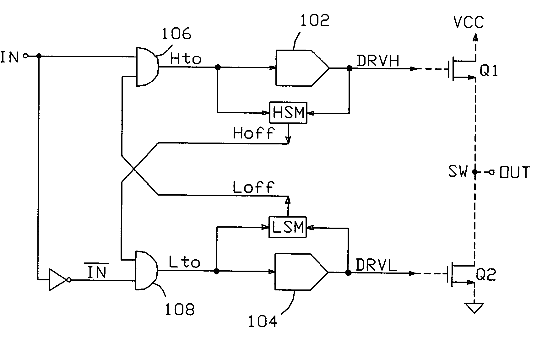
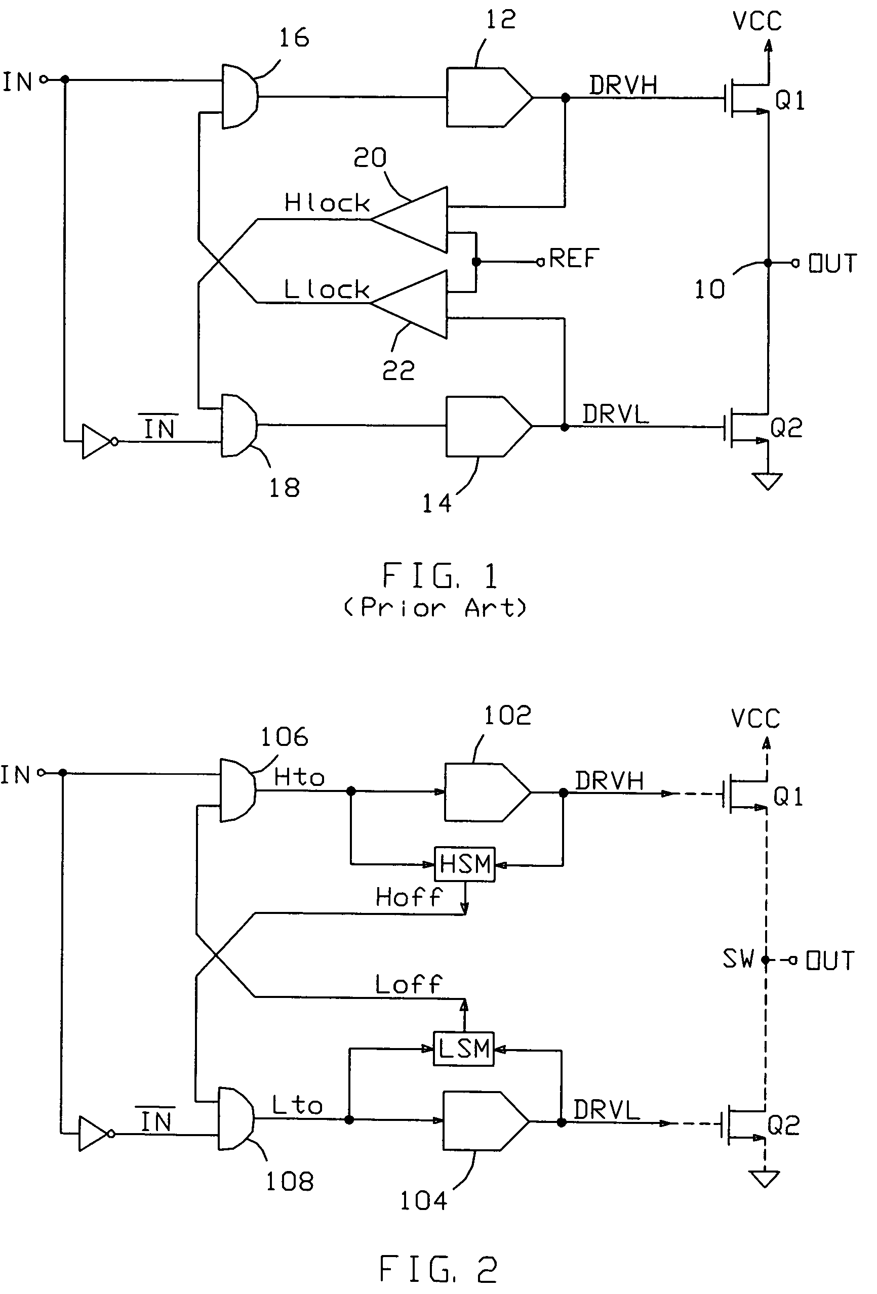
[0023]The present invention is an anti-cross conduction driver control circuit and method which provides reliable prevention of shoot-through currents, regardless of the width of the input pulse or the particular characteristics (including propagation delay) of the driver circuits.

[0024]The basic principles of the invention are illustrated in FIG. 2. The circuit is suitably employed to drive two power devices which are connected in series between a first supply voltage (VCC) and a second supply voltage (which may include ground). In FIG. 2, the power devices are shown as FETs (Q1 and Q2), though bipolar transistors or other types of switching devices might also be driven. The power devices are connected together at a switching node SW, which typically provides a final output (OUT).

[0025]The power devices controlled by the present driver control circuit are driven with respective driver circuits 102 and 104, which are typically referred to as “high-side” and “low-side” drivers, respe...


PUM


Abstract

An anti-cross conduction driver control circuit and method prevent the occurrence of race conditions and avoid cross-conduction between series-connected power devices, typically MOSFETs, controlled in accordance with the present invention. Individual state machines are connected across the inputs and outputs of each power device driver, and are arranged to accurately determine when the driver has completed a task requested of it. Each state machine produces a “lockout” signal based on driver status, which is used to inhibit the operation of the opposite driver under prescribed conditions, and to thereby prevent cross-conduction between the series-connected power devices.

Description

[0001]This application claims the benefit of provisional patent application No. 60 / 585,397 to Audy, filed Jul. 1, 2004.BACKGROUND OF THE INVENTION[0002]1. Field of the Invention[0003]This invention relates to the field of power switch driver circuits, and particularly to driver circuits designed to prevent cross conduction between a pair of series-connected power switches.[0004]2. Description of the Related Art[0005]Many circuits include an output stage consisting of two power switches connected in series, with each switch conducting a respective current to or from a common node which serves as the stage's output. The switches are typically connected between a supply voltage and ground; as such, it is important that only one switch be closed at a time, to prevent “shoot-through” currents from flowing through both switches.[0006]A number of “anti-cross conduction” techniques have been developed to ensure that both switches are not closed at the same time. A typical approach is shown ...

Claims


Application Information

Patent Timeline
Patent Type & Authority Patents(United States)
IPC IPC(8): H03K17/16H03K17/26
CPCH02M1/38H03K17/6871H03K17/162H03K17/08122
Inventor AUDY, JONATHAN M.
Owner ANALOG DEVICES INC
Why Eureka
Try Eureka