
Storage system

a storage system and system technology, applied in the field of storage systems, can solve the problems of difficult to know the configuration of the san accurately, difficult to know the connection environment, and inability to know the configuration change of the san

Inactive Publication Date: 2007-03-06
HITACHI LTD
View PDF19 Cites 24 Cited by
  • Summary
  • Abstract
  • Description
  • Claims
  • Application Information

AI Technical Summary

Benefits of technology

This solution enables unified management of storage system configurations, ensures reliable connection configurations, improves maintenance efficiency, and reduces the likelihood of failures by providing real-time monitoring and alerting for potential issues.

Problems solved by technology

However with this technology the configuration change of a SAN cannot be known, although this configuration changes constantly in order to handle the increases in the data volume to be managed.
In this way, the configuration of the SAN is changed from the initial configuration at construction as time passes, so it is difficult to accurately know the configuration of the SAN.
In other words, it is difficult to know the connection environment, such as the type of HBA the storage device is connected to, and the type of switch through which the storage device is connected.
If a communication failure occurs to a SAN when the connection environment is unknown, the system administrator and the maintenance engineer must first know the configuration of the SAN, which means that it takes time to specify the location and the cause of the failure generation, and operability, until failure recovery, drops.
And “compatibility” issues exist with the connection of each element.
For example, even if no problem occurs when a certain type of switch and a certain type of HBA are combined, a problem may occur if one of the switch and the HBA is changed to a different type.
And the installation of unverified software for an HBA and a switch by the user, for example, may cause unexpected problems.
However the configuration of the storage system at this point has been changed from the initial configuration, and it takes time to accurately know the latest connection environment of the storage system.

Method used


Image

  • Storage system
  • Storage system
  • Storage system

Examples


first embodiment

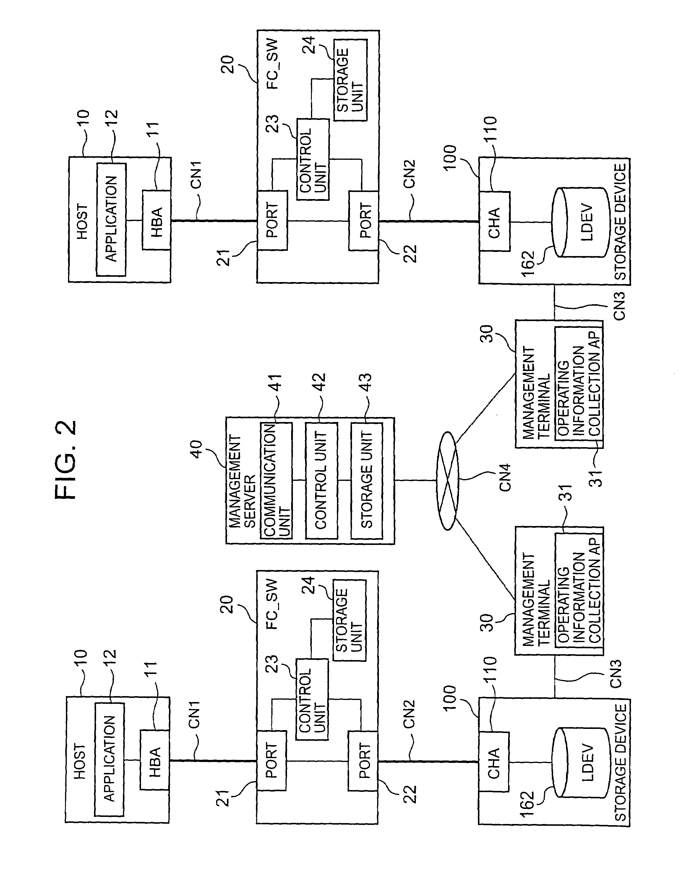
[0094]FIG. 2 is a block diagram depicting the general configuration of the present invention. In FIG. 2, a storage system is shown on both sides, at the right and left. Each storage system is comprised, for example, of a host 10, switch 20, management terminal 30 and storage device 100. Information on the respective configuration of these plurality of storage sub-systems can be unitarily managed by the management server 40. FIG. 2 shows two storage systems, but three or more storage systems may be managed by one management server 40.

[0095]The host 10 is such a computer device as a server machine, for example. The host 10 comprises at least one HBA 11 and application program (hereafter “application”) 12. HBA 11 can perform data communication based on FCP, and conforms to the FC-GS-4 standard. The application 12 is comprised of a data base management program and electronic management program, for example, and accesses the storage device 100 via the HBA 11, and reads / writes the desired...


PUM


Abstract

The present invention unitarily manages the configuration change of a storage system so as to know the latest configuration, and evaluates the reliability in advance when the configuration is changed so that the generation of a failure is suppressed. When the host 1 is connected to the switch 2, the attribute information of HBA 1A and the attribute information of the switch 2 are stored in the connection information storage unit 2C by FDMI (Fabric Device Management Interface) (S1, S2). Each attribute information is associated with each other and is managed as combination information. The storage device 3 acquires the combination information from the switch 2 (S3, S4), and requests the management device 4 to judge the reliability of this combination (S5). The management device 4 judges the combination of the HBA and the switch (S6), and notifies this judgment result to the storage device 3 (S7). When the configuration of the storage system is changed, the reliability of the configuration can be confirmed before starting operation with the configuration after change, and therefore the generation of a failure can be decreased.

Description

BACKGROUND OF THE INVENTIONCROSS-REFERENCE TO RELATED APPLICATIONS[0001]This application relates to and claims priority from Japanese Patent Application No. 2004-370887 filed on Dec. 22, 2004, and the entire disclosure of which is incorporated herein by reference.FIELD OF THE INVENTION[0002]The present invention relates to a storage system.DESCRIPTION OF THE RELATED ART[0003]A storage system comprises one or more storage devices which are used by a plurality of host computers (hereafter “host”), for example. Each host and storage device are connected by an inter-connection device, such as a fiber channel switch and a hub.[0004]A storage device is also called a disk array device or a storage sub-system, for example, and is comprised of many disk drives laid out in an array. The storage device provides a storage area based on RAID (Redundant Array of Independent Disks), for example. On the physical storage area of each disk drive, a logical volume (logical device), which is a logical ...

Claims


Application Information

Patent Timeline
Patent Type & Authority Patents(United States)
IPC IPC(8): G06F13/00G06F15/177G06F11/00G06F13/40G06F15/173
CPCG06F3/0605G06F3/0617G06F3/0632G06F3/0653H04L41/147G06F11/0727H04L41/0853G06F3/067G06F3/0601G06F11/076G06F2003/0697
Inventor HARIMA, TORUNAMBA, TATSUOUCHIUMI, KATSUHIROFUTAWATARI, NAOKIISOBE, ITARU
Owner HITACHI LTD
Learn More