
Method and system for logic-level circuit modeling

a logic-level circuit and logic-level technology, applied in the direction of cad circuit design, program control, instruments, etc., can solve the problems of inability to include the constraints of core logic in the model, no way to apply original constraints, etc., and achieve the effect of more accurate timing models and simplified yet accura

Inactive Publication Date: 2007-03-06
CADENCE DESIGN SYST INC
View PDF16 Cites 14 Cited by
  • Summary
  • Abstract
  • Description
  • Claims
  • Application Information

AI Technical Summary

Benefits of technology

[0015]An object of the present invention is to provide a simplified yet accurate model of a logic circuit for use in designing circuits. An alternate or additional object of the present invention is to provide for more accurate timing models. Yet another alternate or additional object of the present invention is to provide clock-context independent timing analysis. Still a further alternate or additional object of the present invention is to provide models of an actual circuit which can be generated each time without needed to be stored on a memory medium, such as a disk. These and other objects and advantages are described further in the figures, specification and claims.

Problems solved by technology

Approaches which preserve only interface logic, while beneficial in that actual logic is preserved, have the disadvantage that there often is no way to apply original constraints when using the model if constrained objects are no longer present.
In other words, constraints on core logic cannot be included in the model.

Method used


Image

  • Method and system for logic-level circuit modeling
  • Method and system for logic-level circuit modeling
  • Method and system for logic-level circuit modeling

Examples


Embodiment Construction

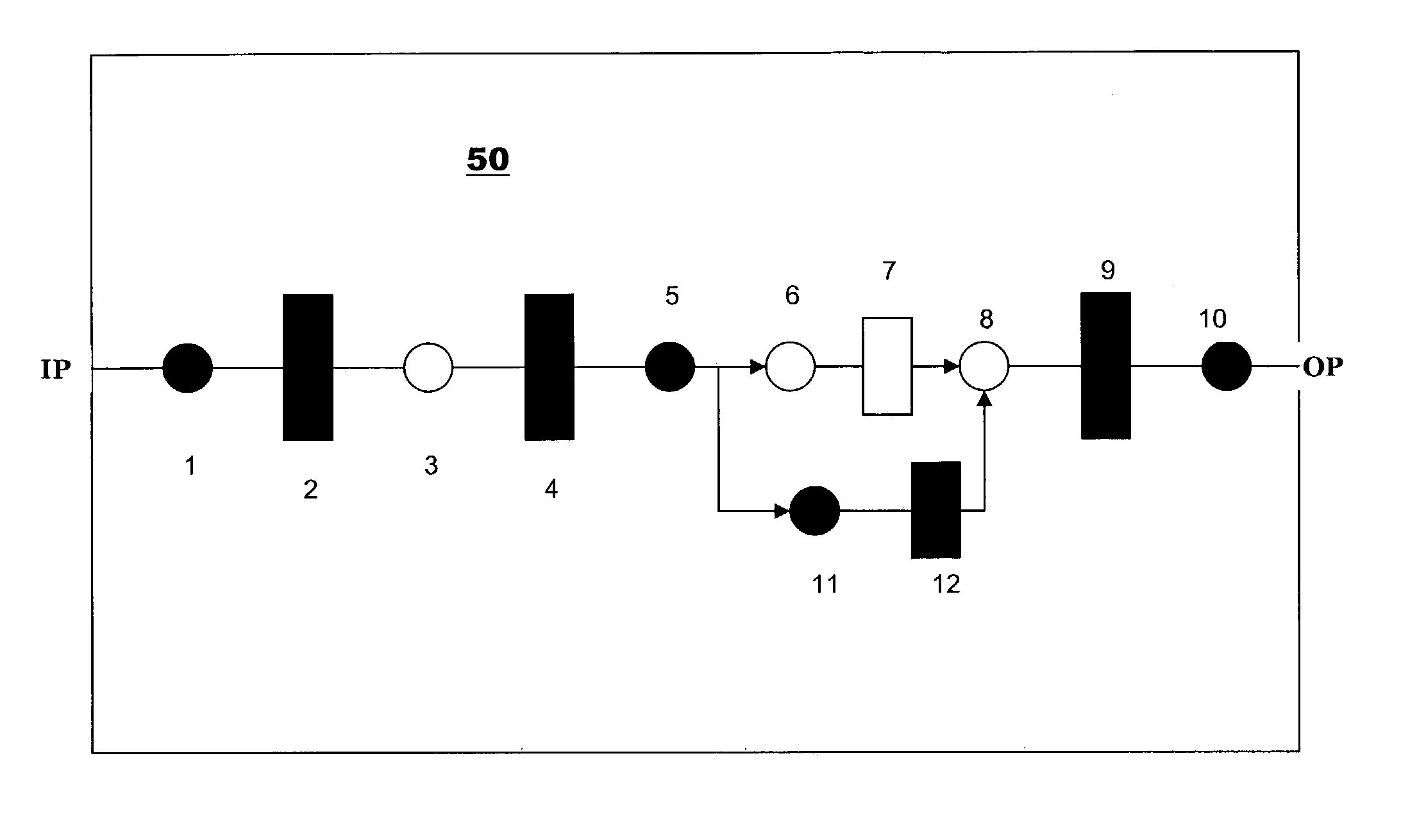
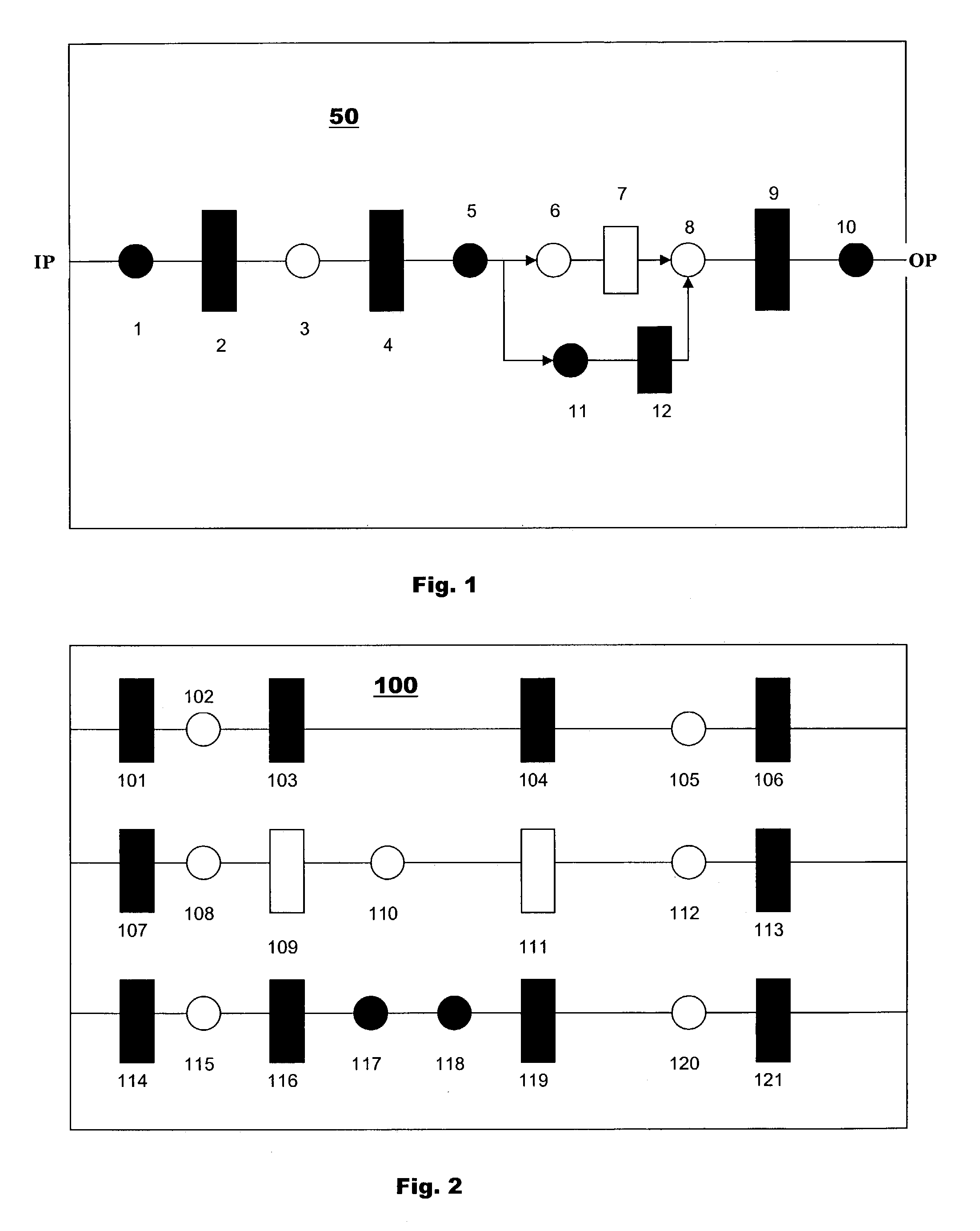
[0040]FIG. 1 shows the basic concept for shell / core partitioning, in which logic components (with inputs on the left side and outputs on the right) for an interface path are identified and defined as shell logic. An approach to this partitioning is described in more detail in U.S. patent application Ser. No. 09 / 678,150, entitled “A TIMING VERIFICATION METHOD EMPLOYING DYNAMIC ABSTRACTION IN CORE / SHELL PARTITIONING”, filed Oct. 3, 2000 and hereby incorporated by reference herein.

[0041]A representative block 50, which is a logic-level block, is created, for example, by synthesizing the register transfer or RTL level of the circuit designed by a designer using, for example, Verilog or VHDL. The designer adds any preliminary constraints to the block.

[0042]The block 50 has a single input IP, memory elements 2, 4, 7, 9 and 12, gates 1, 3, 5, 6, 8, 10 and 11, and an output pin OP. The memory elements 2, 4, 7, 9 and 12, may be, for example edge triggered D-type flip-flops, and all run on a ...


PUM


Abstract

A method for generating a model for a circuit having logic components is provided. The method includes identifying interface path logic components of the logic components so as to define shell logic, and identifying at least one of the logic components on which a constraint has been annotated so as to define constrained logic components. A subset of the logic components to preserve is then determined, the subset including the shell logic and the constrained logic components so as to define preserved logic. The model is then formed from the preserved logic. A highly accurate model can thus be created, while reducing computational and memory requirements. On-the-fly regeneration of the model is also possible, as is dominant path logic preservation.

Description

CROSS-REFERENCE TO RELATED APPLICATIONS[0001]The present application claims priority to U.S. Provisional Patent Application No. 60 / 371,696, filed Apr. 11, 2002 and hereby incorporated by reference herein.BACKGROUND INFORMATION[0002]The present invention relates to timing analysis for electronic circuits, for example, very large-scale integrated (VSLI) circuits.[0003]Before a circuit design is finalized for fabrication, timing analysis tools are used to verify the proper timing of the circuit. The clock or clocks for the circuit must trigger the various circuit components are proper times. The timing and I / O characteristics of the various basic circuit components, including resistors, transistors and wiring, are known, so that timing diagrams may be created by a circuit designer for very small circuits to ensure that timing is proper.[0004]However, such timing diagrams are impractical for all but the smallest circuits. Thus software tools have been developed to aid circuit designers....

Claims


Application Information

Patent Timeline
Patent Type & Authority Patents(United States)
IPC IPC(8): G06F17/50
CPCG06F17/5022G06F30/33
Inventor HAHN, MARK STEVEN
Owner CADENCE DESIGN SYST INC
Learn More