

Float retractable landing gear
- Summary
- Abstract
- Description
- Claims
- Application Information
AI Technical Summary
Benefits of technology
Problems solved by technology
Method used
Image

Examples
Embodiment Construction
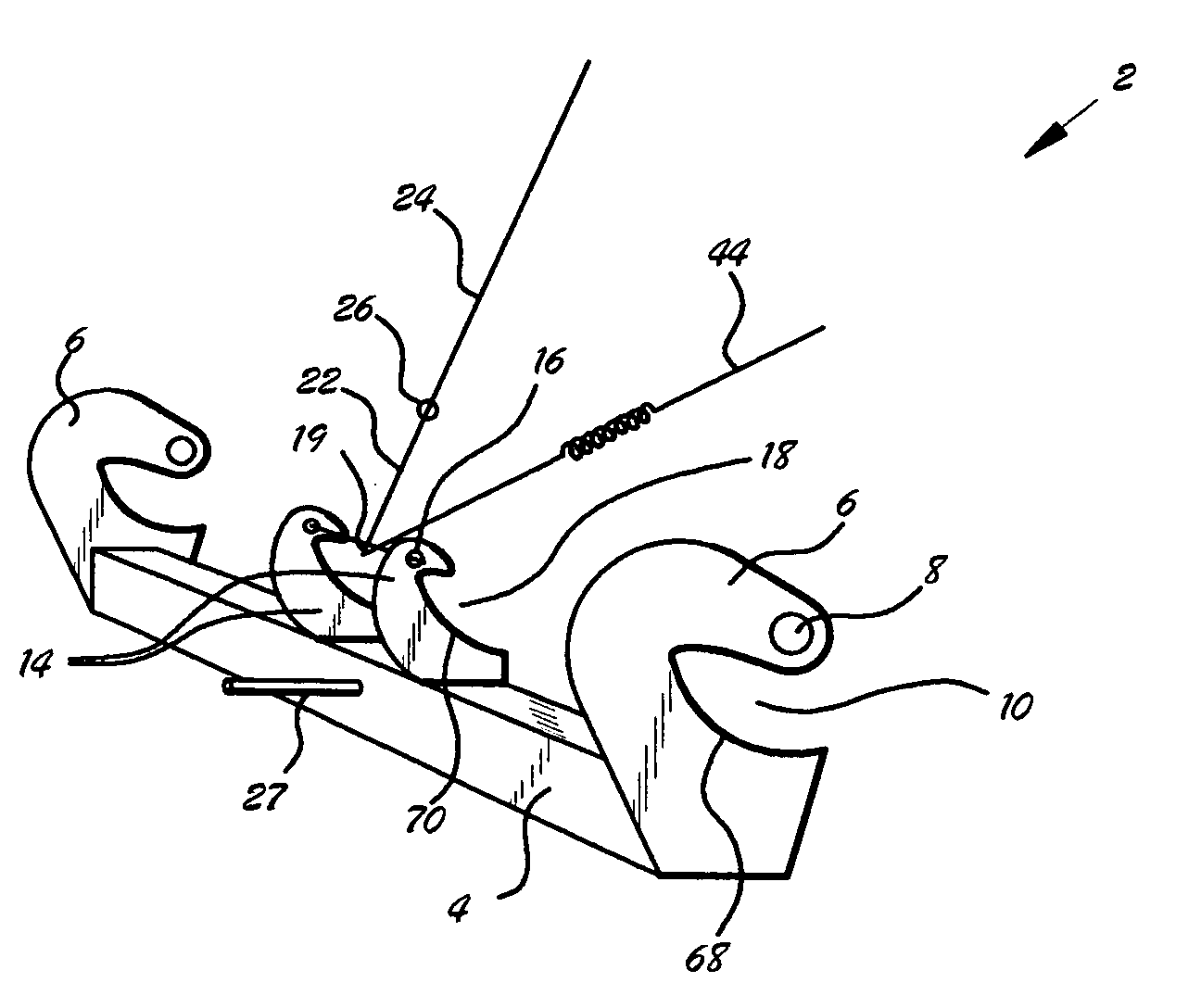
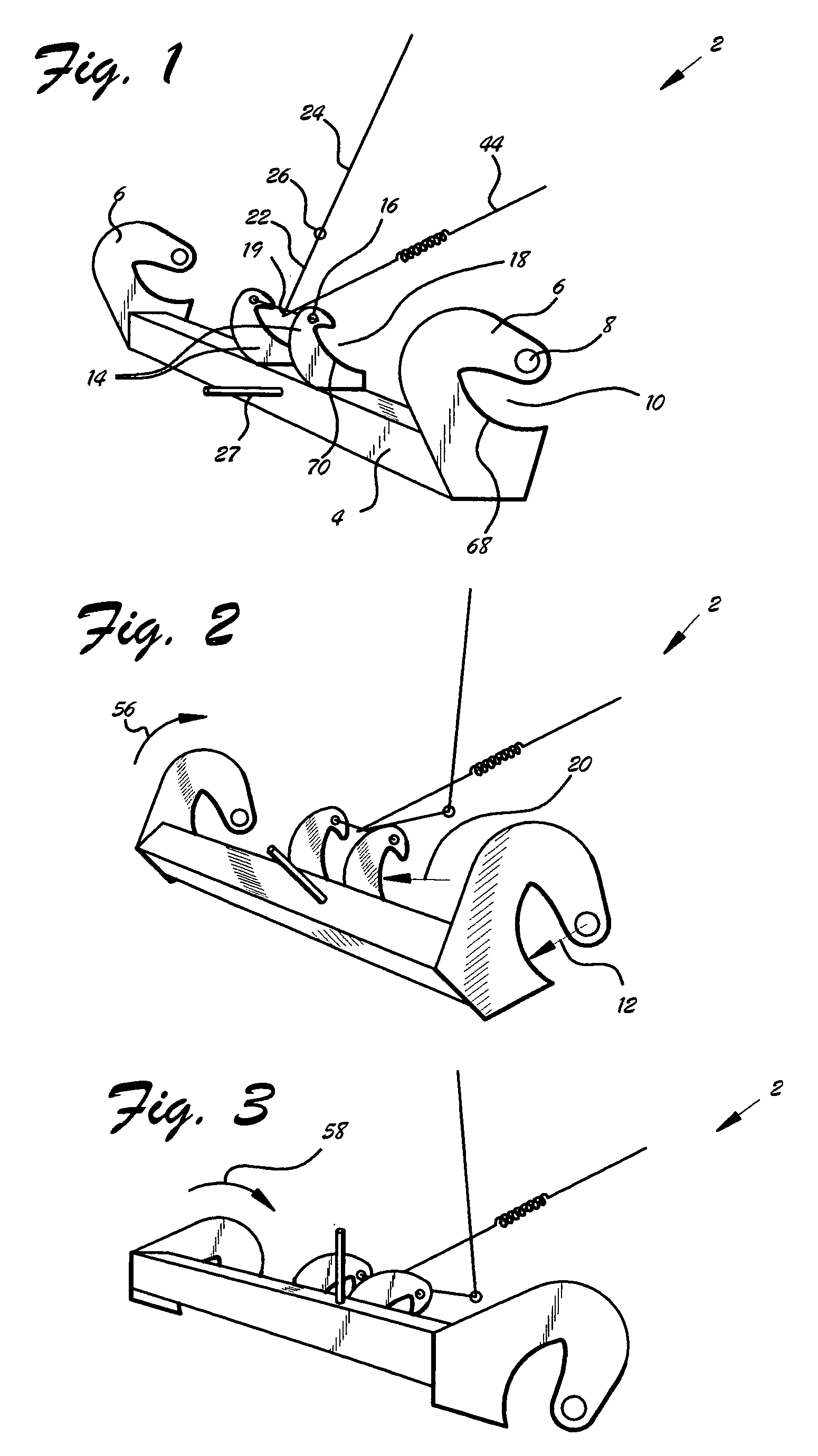
[0037]FIGS. 1–3 are side isometric views of most of the components of float retractable landing gear 2 retracting from the fully extended position of FIG. 1 to the fully retracted position of FIG. 3. Float retractable landing gear 2 comprises a hinge 6 attached at either extreme of spine 4. At least one strut ear 14 is attached to spine 4 between hinges 6. Wheel mount 27 is also attached to spine 4, and is sized to accept an appropriately sized wheel.
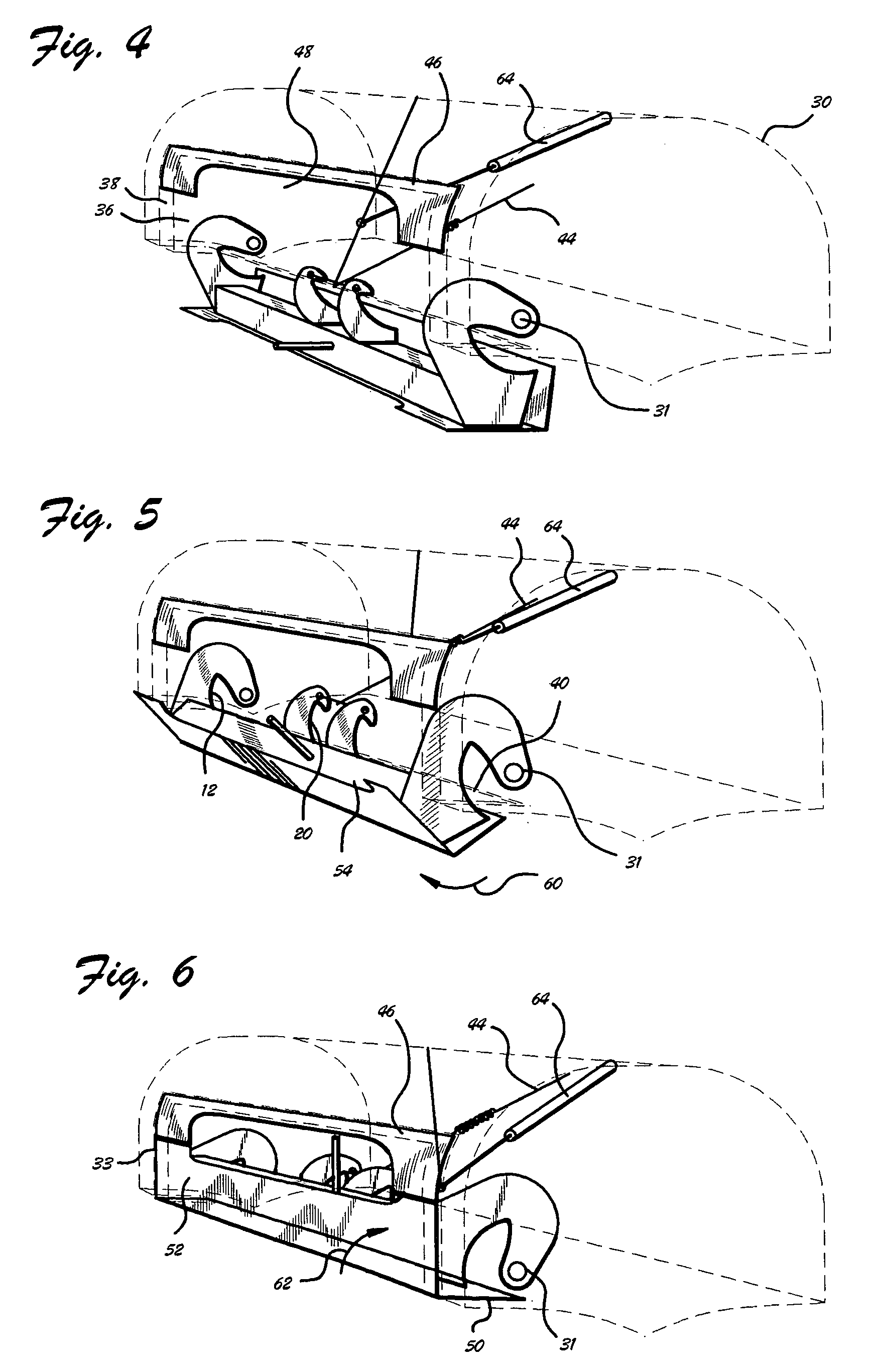
[0038]Each hinge 6 comprises a hinge pivot point 8 at an extreme of hinge 6 opposite spine 4, and a hinge cutout 10 between hinge pivot point 8 and spine 4. Hinge cutout 10 comprises hinge cutout arc 68 of hinge cutout arc radius 12. Hinges 6 rotate relative to float 30 about hinge pivot point 8, as may be observed in FIGS. 4–6.
[0039]Each strut ear 14 comprises a strut attach point 16 at an extreme of strut ear 14 opposite spine 4, and a strut ear cutout 18 between strut attach point 16 and spine 4. Strut ear cutout 18 comprises strut e...
PUM
 Abstract
Description
Claims
Application Information