

Termination for optic fiber
a technology of optic fiber and terminal elements, applied in the direction of optics, instruments, optical light guides, etc., can solve the problems of difficult miniaturization of fiber optic terminal elements, a significant challenge for fiber optic termination, and bulky typical hermetically sealed components
- Summary
- Abstract
- Description
- Claims
- Application Information
AI Technical Summary
Benefits of technology
Problems solved by technology
Method used
Image

Examples
Embodiment Construction
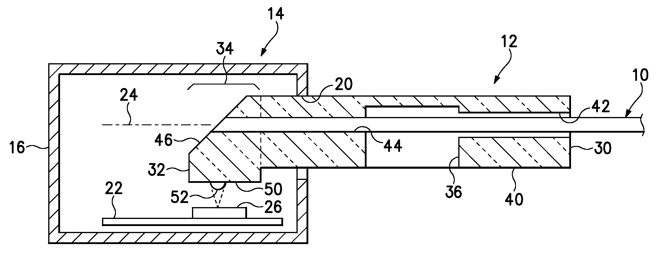
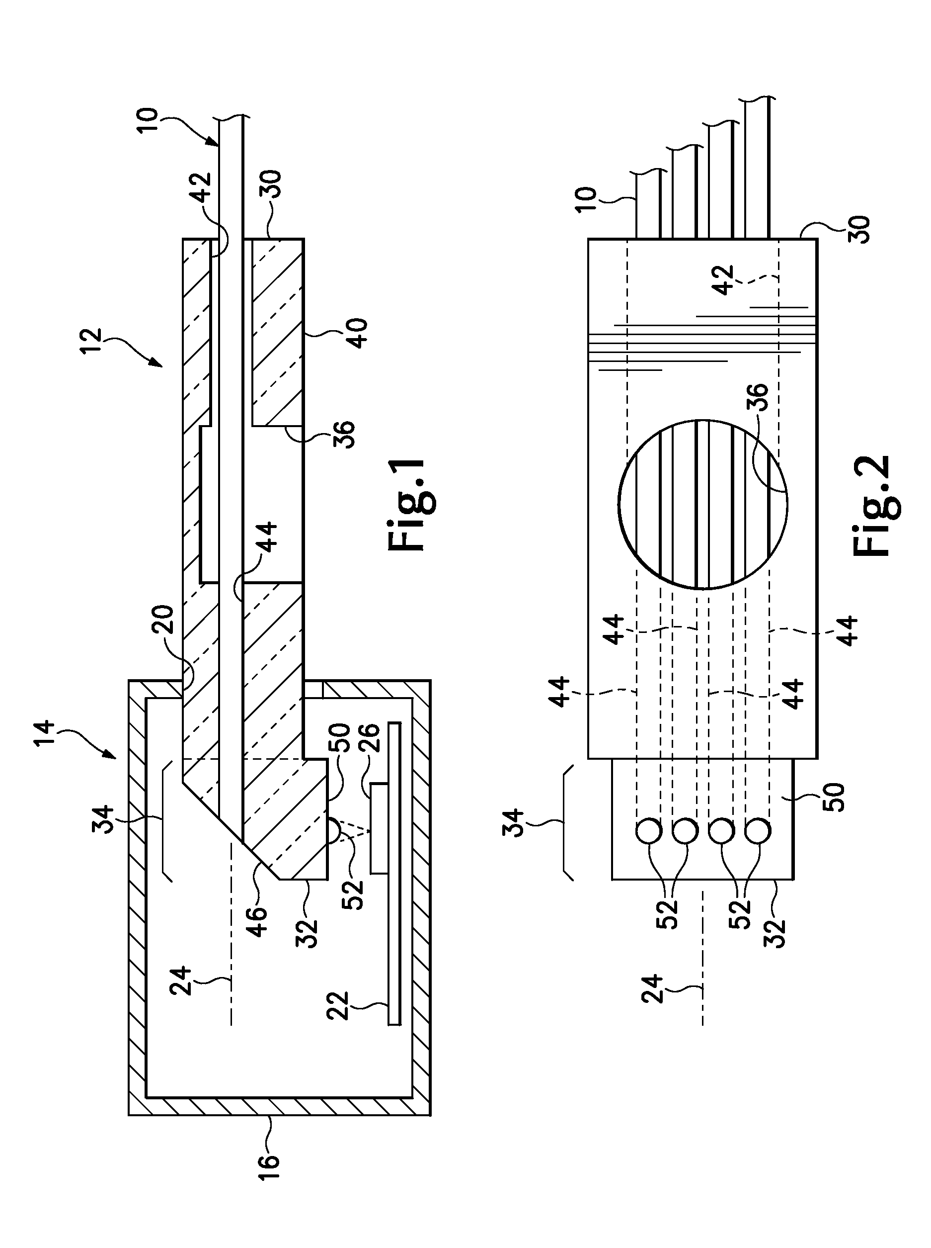
[0011]FIG. 1 shows an optical fiber cable 10 with a terminal element 12 connected for interfacing with an electronic instrument or communications module 14. The fiber optic cable has four multi-mode optical fibers that extend some distance to a remote communications device (not shown) that is sending and / or receiving signals or data to or from the module 14. In alternative embodiments the fibers may be single-mode or any other type, and may be used in a bundle of any number of fibers, or with a single fiber.
[0012]The module 14 may be any type of electronics or communications instrument or component thereof that requires communication with a remote external device. The module may be used for a telecom local station, or other communications or relay stations used for Internet or other computer networks, including networks found on vehicles such as automobiles and aircraft. The embodiment is well-suited for applications where harsh environmental conditions are experienced, and where hi...
PUM
 Abstract
Description
Claims
Application Information