
Cross-flow wind turbine

a wind turbine and cross-flow technology, applied in the field of wind turbines, can solve the problems of inefficiency of axial-flow wind turbines, inability to extract power from wind energy, and high cost of braking systems and systems for feathering the blade angle, and achieve the effect of increasing efficiency

Inactive Publication Date: 2007-03-13
TERRA MOYA AQUA
View PDF93 Cites 27 Cited by
  • Summary
  • Abstract
  • Description
  • Claims
  • Application Information

AI Technical Summary

Benefits of technology

"The present invention is a cross-flow wind turbine that improves efficiency by capturing wind energy in a better way. It uses a blocking stator to create a pressure differential between the leading and trailing faces of the rotor blades, which causes a force to rotate the blades. This results in a more effective capture of wind energy, even at different wind speeds. Overall, the invention increases the amount of wind energy that can be captured and converted into useful energy."

Problems solved by technology

Hence, expensive braking systems and systems for feathering the angle of the blades must be used to control the speed of axial-flow wind turbines in moderately strong to strong winds.
As a result, axial-flow wind turbines are inefficient in moderately strong to strong winds and, as such, are unable to extract power from wind energy when it is at its greatest energy producing level.
Further, axial-flow wind turbines are very dangerous to birds.
Birds are frequently killed by the inability of these avians to sense the presence of the rapidly moving blades of the axial-flow wind turbines.
Cross-flow wind turbines have certain advantages over axial-flow wind turbines, but have not previously been seriously considered as a source of alternative energy because of the comparatively lower efficiencies with respect to the axial-flow wind turbines.

Method used


Image

  • Cross-flow wind turbine
  • Cross-flow wind turbine
  • Cross-flow wind turbine

Examples


Embodiment Construction

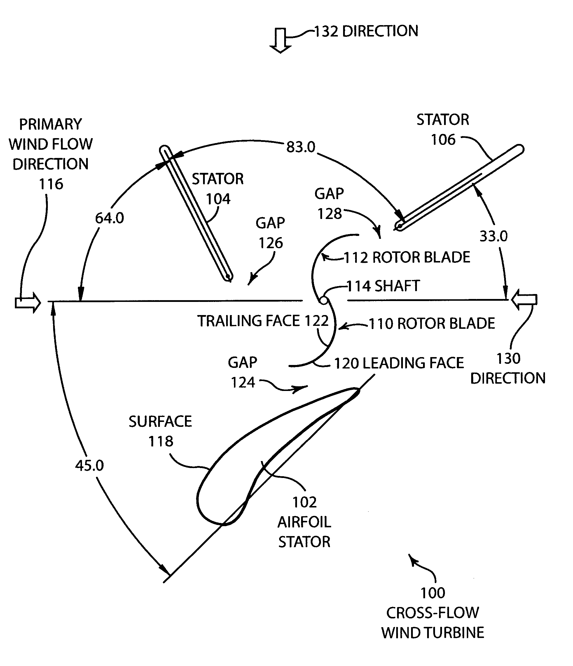
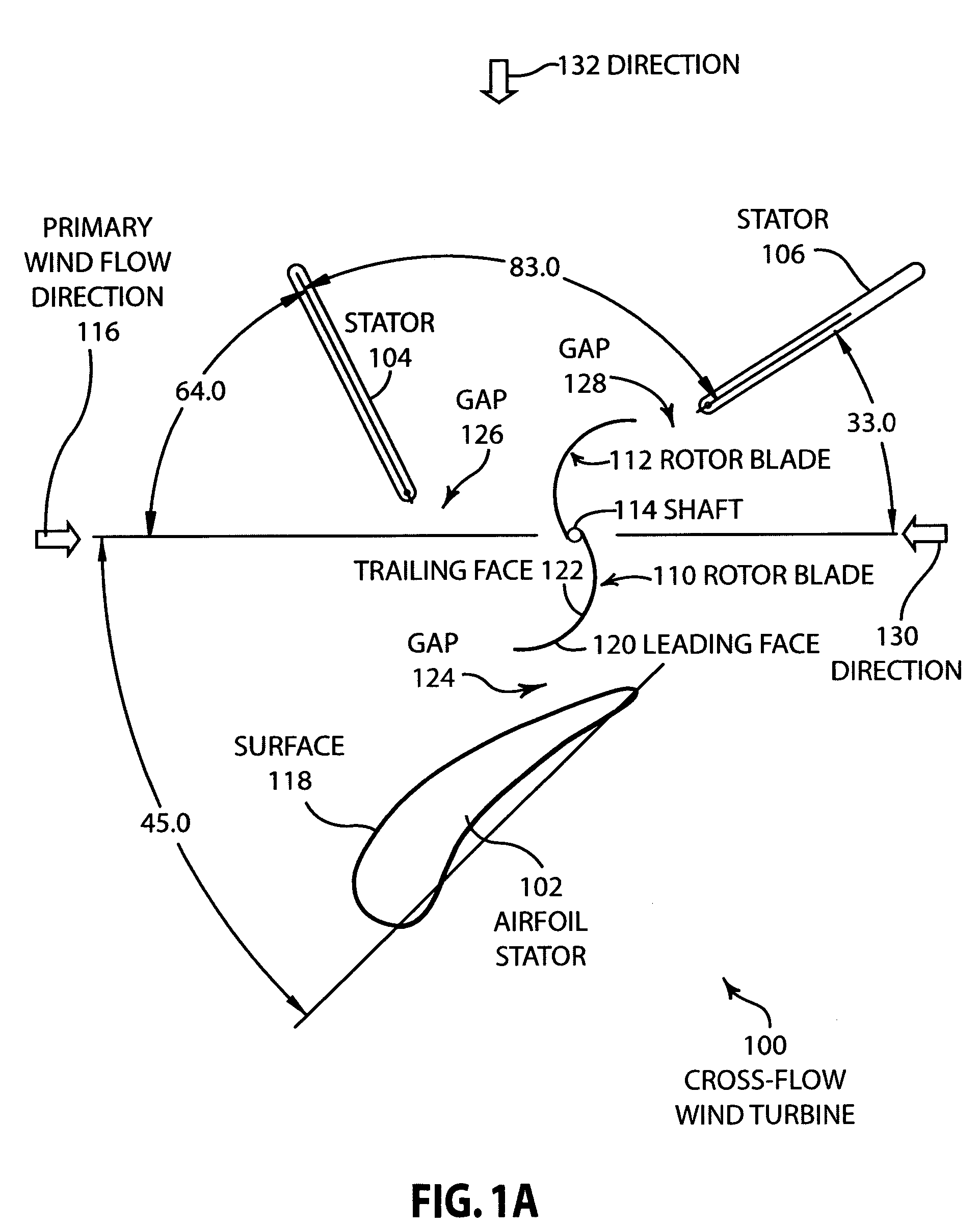
[0052]FIG. 1A is an illustration of one embodiment of a cross-flow wind turbine 100. The cross-flow wind turbine includes an air foil stator 102 that is fixed, stator 104 that is fixed and stator 106 that is also fixed. The rotor 108 rotates in response to forces created by wind. Rotor 108 includes rotor blade 110, rotor blade 112 and a rotating shaft 114. The cross-flow wind turbine 100, illustrated in FIG. 1A, is designed for maximum efficiency for wind flowing in a primary direction 116 which may be aligned with the prevailing wind at a specific geographical location. However, the cross wind flow turbine 100 also produces high efficiencies for winds flowing from other directions, as described in more detail below with respect to FIG. 3.

[0053]As also shown in FIG. 1A, the angular positions of the stators are shown with respect to the primary wind flow direction 116. The cross-flow wind turbine 100 that is illustrated in FIG. 1A shows each of the elements generally in their relativ...


PUM


Abstract

Disclosed are various embodiments of cross-wind turbines that are capable of providing high efficiencies over a wide range of wind velocities. An airfoil stator causes wind to accelerate along its surface and creates a low pressure area on the leading face of the rotor blade during the power stroke. A blocking stator blocks wind from impeding the movement of the rotor blades during the return cycle and directs wind onto the trailing face of the rotor blades during the power cycle. A large pressure differential is created between the leading face of the rotor blade and the trailing face of the rotor blade during the power cycle which creates a large amount of force that rotates the rotor blade about the central shaft. In some embodiments, gaps are provided between the inside edge of the rotor blade and a stationary shaft which vents wind collected by the rotor blade during certain portions of the rotation cycle. The vented wind increases the pressure on the trailing face of the rotor blades during the return cycle to further assist in the efficiency of this system.

Description

CROSS REFERENCE TO RELATED APPLICATIONS[0001]This application is a continuation-in-part of U.S. patent application Ser. No. 10 / 831,515 entitled “Wind Turbine Having Airfoils for Blocking and Directing Wind and Rotors With or Without a Central Gap” by Ronald Taylor and Scott Taylor, filed Apr. 23, 2004, now U.S. Pat. No. 60 / 467,773 which claims the benefit of and priority to U.S. Provisional Patent Application Serial No. 60 / 467,773 entitled “Wind Turbine” by Ronald Taylor and Scott Taylor, filed Apr. 30,2003. The present patent application further claims the benefit of U.S. Provisional Patent Application Serial No. 60 / 639,448, filed on Dec. 23, 2004, entitled “Cross-Flow Wind Turbine.” The entire contents of the above mentioned applications are hereby specifically incorporated herein by reference for all they disclose and teach.BACKGROUND OF THE INVENTION[0002]a. Field of the Invention[0003]The present invention pertains generally to wind turbines and more particularly to cross-flow ...

Claims


Application Information

Patent Timeline
Patent Type & Authority Patents(United States)
IPC IPC(8): F03D3/04
CPCF03D3/04F03D3/0409F05B2240/121F05B2240/13Y10S416/09F05B2240/30Y02E10/74Y10S415/907Y10S416/04F05B2240/213F03D9/25F03D15/10F03D3/0427
Inventor TAYLOR, SCOTT J.TAYLOR, RONALDCOCHRAN, BRAD C.BANKS, DAVID
Owner TERRA MOYA AQUA
Learn More