Photomultiplier and radiation detector

a radiation detector and photomultiplier technology, applied in the field of photomultiplier and radiation detector, can solve the problems of impeded high-density realization and high-integrated mounting, and achieve the effect of preventing the mixing of noise into the electrical signal taken out of the anode pin and positioned easily

Active Publication Date: 2007-03-13
HAMAMATSU PHOTONICS KK
View PDF17 Cites 4 Cited by
  • Summary
  • Abstract
  • Description
  • Claims
  • Application Information

AI Technical Summary

Benefits of technology

[0009]With this photomultiplier, since the second side tube is not interposed between the first side tube and the stem in the radial direction of the side tubes, and the first side tube is joined to the second side tube in the state of being directly capped onto the portion of the stem that protrudes out from the open end face of the second side tube, the enlargement of the side tube diameter due to overlapping of the first side tube and the second side tube can be avoided. Also, in joining the first side tube and the second side tube, the first side tube can be positioned readily with respect to the second side tube by making the first side tube contact the stem that protrudes from the open end face of the second side tube.
[0010]Also preferably, the stem has an insulating base member through and to which the stem pins, including an anode pin electrically connected to the anode, are passed and joined, and a peripheral portion, near the anode pin, of the inner side (that is, the side facing the interior of the sealed container) of the base member is arranged as a chamfered shape. In this case, since the stem that is surrounded by the conductive side tubes is arranged as the insulating base member and the peripheral portion, near the anode pin, of the inner side of the base member is arranged as the chamfered shape, the creeping distance along the base member (insulator) between the triple junction, at which the conductive anode pin, the insulating base member joined to the anode pin, and vacuum intersect, and the conductive side tubes is made adequately long in comparison to the case where there is no chamfered shape. The mixing of noise into the electrical signal taken out from the anode pin is thus adequately prevented.

Problems solved by technology

As a result of such enlargement of the outer diameter of the side tube, the realization of high-density, highly-integrated mounting is impeded.

Method used


Image

  • Photomultiplier and radiation detector
  • Photomultiplier and radiation detector
  • Photomultiplier and radiation detector

Examples


first embodiment

[0060][First Embodiment]

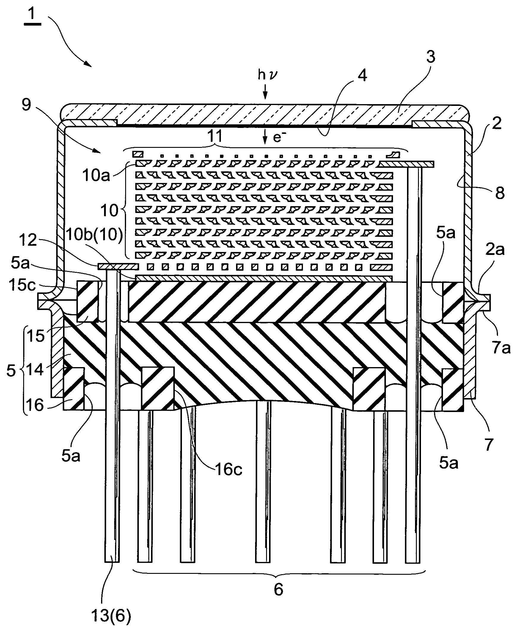
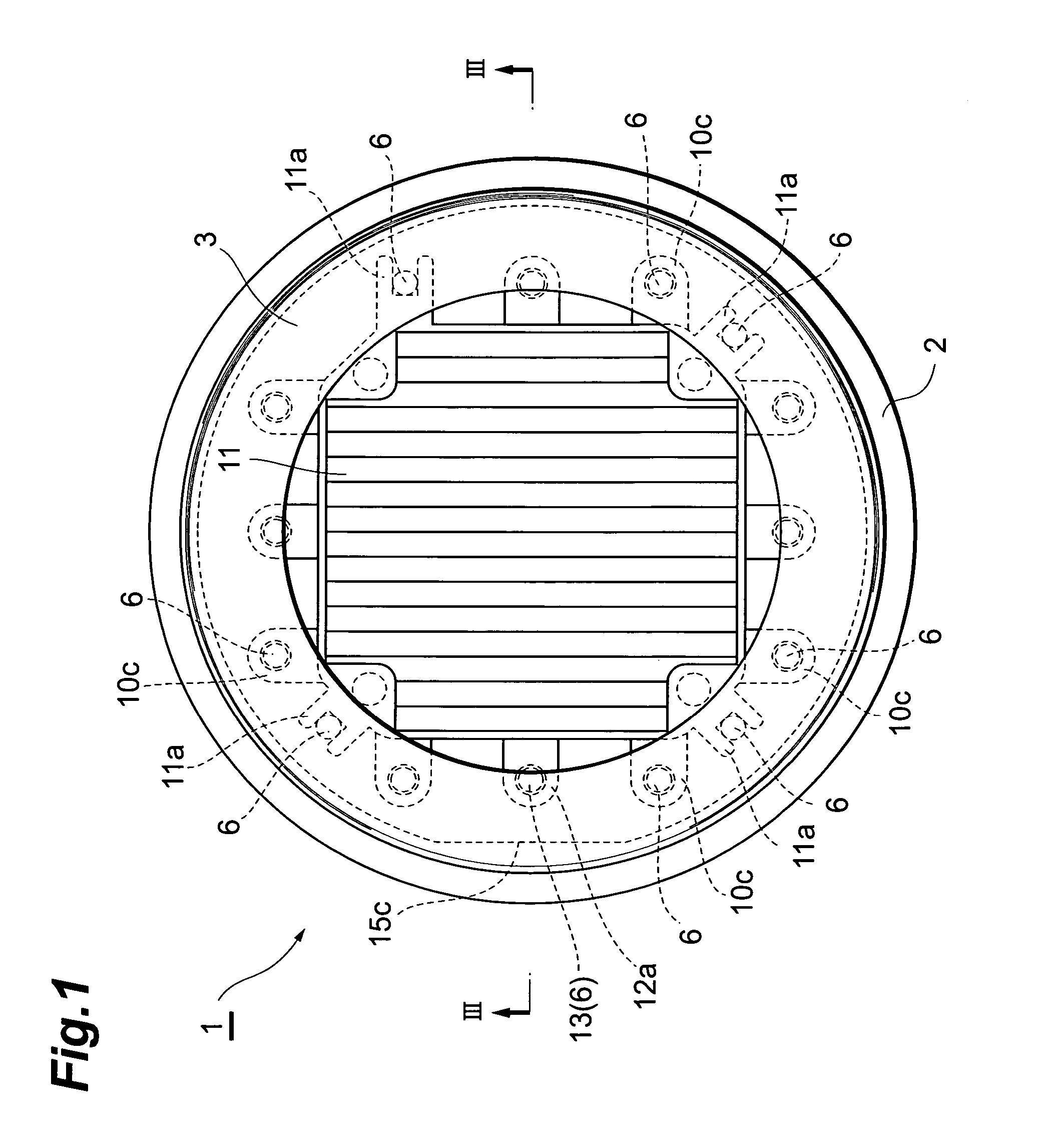
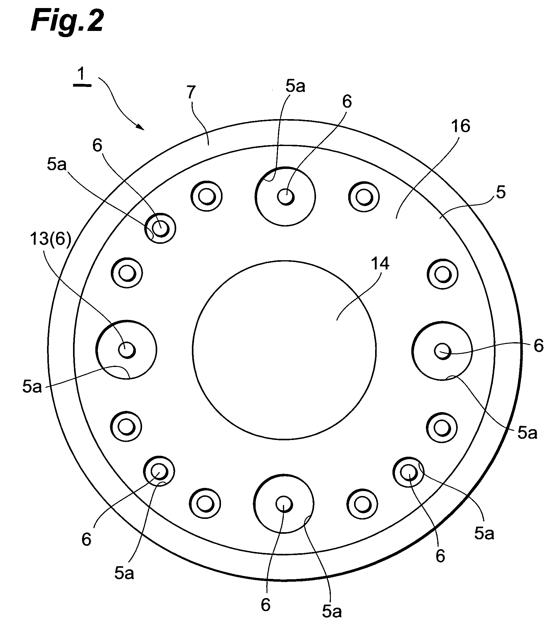
[0061]FIG. 1 and FIG. 2 are a plan view and a bottom view, respectively, of an embodiment of a photomultiplier by this invention, and FIG. 3 is a sectional view taken along line III—III in FIG. 1. In FIG. 1 to FIG. 3, a photomultiplier 1 is arranged as a device that emits electrons upon incidence of light from the exterior and multiplies and outputs the electrons as a signal.

[0062]As shown in FIG. 1 to FIG. 3, the photomultiplier 1 has a metal side tube (first side tube) 2 with a substantially cylindrical shape. As shown in FIG. 3, a glass light receiving plate 3 is fixed in an airtight manner to an open end at the upper side (one side) of the side tube 2, and a photoelectric surface 4, for converting the light made incident through the light receiving plate 3 into electrons, is formed on the inner surface of the light receiving plate 3. Also, a disk-like stem 5 is positioned at an open end at the lower side (other side) of the side tube 2 as shown in FIG. 2 ...

second embodiment

[0096][Second Embodiment]

[0097]As shown in FIG. 29, the photomultiplier 28 of a second embodiment has a stem 29 arranged as a two-layer structure of a disk-like base member 30, of the same quality as the base member 14, and the upper holding member 15, joined to the upper side (inner side) of the base member 30, and thus differs from the photomultiplier 1 of the first embodiment, wherein the stem 5 is arranged as a three-layer structure of the base member 14, the upper holding member 15, and the lower holding member 16.

[0098]That is, the stem 29 of the photomultiplier 28 is not provided with the lower holding member 16, and the base member 30 has, along outer peripheral portions of the base member 30, a plurality (15) of openings 30a, with each of which the diameter of the upper half is made substantially equal to the outer diameter of each stem pin 6 as shown in FIG. 30 and the diameter of the lower half is made larger than the outer diameter of each stem pin 6 as shown in FIG. 31....

third embodiment

[0131][Third Embodiment]

[0132]As shown in FIG. 39, a photomultiplier 34 of a third embodiment has a stem 35 arranged as a single-layer structure of a disk-like base member 36, of the same quality as the base member 14, and thus differs from photomultiplier 1 of the first embodiment, wherein the stem 5 is arranged as a three-layer structure of the base member 14, the upper holding member 15, and the lower holding member 16.

[0133]That is, the stem 35 of the photomultiplier 34 is not provided with the upper holding member 15 and the lower holding member 16, and the base member 36 has, along outer peripheral portions of base member 36, a plurality (15) of openings 36a, with each of which the diameter of an intermediate portion is made substantially equal to the outer diameter of each stem pin 6 and the diameters of upper and lower portions are made larger than the outer diameter of each stem pin 6 as shown in FIG. 39 to FIG. 41. Of the openings 36a of the base member 36, the upper and l...


PUM

PropertyMeasurementUnit
phase angleaaaaaaaaaa
photoelectricaaaaaaaaaa
shapeaaaaaaaaaa

Abstract

In a photomultiplier, a ring-like side tube is not interposed between a side tube and a stem in the radial direction, and the side tube is joined to the ring-like side tube in a state of being directly capped onto a portion of the stem that protrudes out from an open end face at the upper side of the ring-like side tube. The enlargement of the photomultiplier in the radial direction due to overlapping of the side tube and the ring-like side tube can thereby be restricted and a high density, a high degree of integration, etc., can be realized in mounting the photomultiplier.

Description

BACKGROUND OF THE INVENTION[0001]1. Field of the Invention[0002]This invention concerns a photomultiplier that makes use of the photoelectric effect and a radiation detector that uses this photomultiplier.[0003]2. Related Background of the Invention[0004]As one type of photomultiplier, a so-called head-on photomultiplier is known. With this head-on photomultiplier, a sealed vacuum container is arranged by providing a light receiving plate at an end portion at one side of a cylindrical side tube and providing a stem at an end portion at the other side of the side tube, and a photoelectric surface is disposed on the inner surface of the light receiving plate. An arrangement is provided wherein an electron multiplier unit, with a plurality of stages of dynodes, and an anode are layered and positioned opposite the photoelectric surface, and a plurality of stem pins, respectively connected to the respective dynodes and the anode, are insertedly mounted in the stem so as to lead to the ex...

Claims


Application Information

Patent Timeline
Patent Type & Authority Patents(United States)
IPC IPC(8): H01J21/20H01J43/04
CPCH01J43/28
Inventor SHIMOI, HIDEKIKYUSHIMA, HIROYUKI
Owner HAMAMATSU PHOTONICS KK
Why Eureka
Try Eureka