Heating-cooling system for a nozzle

a cooling system and nozzle technology, applied in the field of heaters, can solve the problems of premature cross-linking and ruin the fluid in the heated region, and achieve the effect of reducing the viscosity of the fluid and reducing the effect of cross-linking

Active Publication Date: 2007-03-13
VERRILLI BRIAN LEONARD
View PDF2 Cites 7 Cited by
  • Summary
  • Abstract
  • Description
  • Claims
  • Application Information

AI Technical Summary

Benefits of technology

[0027]Accordingly, the main object of this invention is a novel nozzle heater-cooler that can be removed from the nozzle hub with no tools, requires no tools to assemble or disassemble and can be easily serviced. Each sub-assembly is easily removed and replaced. A unique heating device, approximately the size of a quarter, enables a control system to spike the temperature at the instant of dispensing to reduce viscosity, allowing fluid to flow through the exit aperture with less pressure, reduced surface tension and elastic behavior at break off. What is noteworthy and equally important is a rapid cool down after a temperature spike. Prolonged periods of exposure of fluid at temperature can drive off volatiles, initiate cross-linking prematurely and ruin the fluid in the heated region for deposit on the substrate. This heater prevents these problems and meets the stringent requirement for the fluid string to behave plastically and snap back to the dispensing point, not string or pull apart like Turkish taffy, and works in concert with the nozzle, achieving precise control of the environment surrounding the nozzle. Heat is introduced conductively through the flat bottom surface of the hub. Cooling occurs convectively along each face of the hexagonal geometry.
[0028]The hub to which the heater-cooler is attached is designed for use in a heated application and contains a high percentage of copper. Currently, two designs exist for the hub. The concept behind each design is different, according to the sensitivity of the dispensing process to the thermal response rate. Initially, hubs were brazed to the core enabling fast heat transfer from the hub to the core. This design trades increased cost for superior advantage in thermal response rate.
[0029]The nozzle heater-cooler reduces cost to the consumer by allowing the systems on which it is used to be more productive at higher levels of performance, reducing waste and permits the systems that require its use to be made more economical and more useful in the relevant industry. These and other objects of the invention will become clearer when one reads the following specification, taken together with the drawings that are attached hereto. The scope of protection sought by the inventor may be gleaned from a fair reading of the claims that conclude this specification.

Problems solved by technology

Prolonged periods of exposure of fluid at temperature can drive off volatiles, initiate cross-linking prematurely and ruin the fluid in the heated region for deposit on the substrate.

Method used


Image

  • Heating-cooling system for a nozzle
  • Heating-cooling system for a nozzle
  • Heating-cooling system for a nozzle

Examples


Embodiment Construction

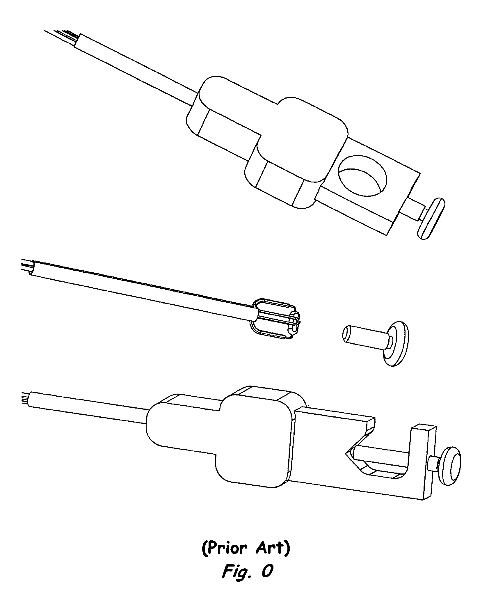
[0040]Referring now to the drawings wherein the showings are for the purpose of illustrating preferred embodiments of the invention only and not for the purpose of limiting it. FIG. 0 Prior Art nozzle heaters used for resistive heating. The first version fits around the hub using a thumbscrew. It is the first image in FIG. 0. The second version clamps around syringe tube type nozzles that are the lower most images of the three. The center view is an image of the internal electrical components that are the basis for the function. It is simply a 100 Ω resistor and a thermocouple. This is the configuration in use by this industry to heat the nozzle fluid path. All versions have the same electrical configuration, the components are inserted into the aluminum housing and insert molded using an elastomer.

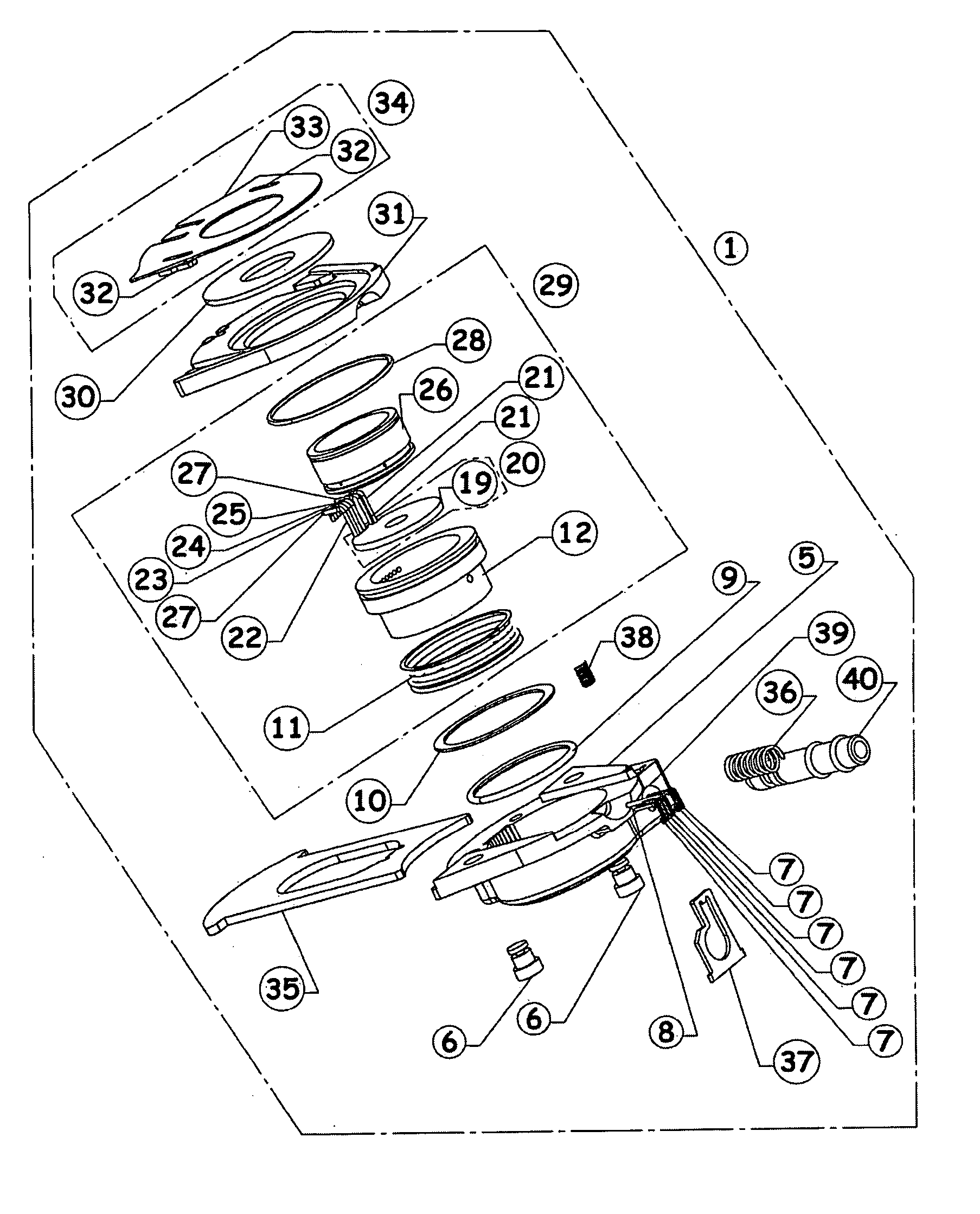
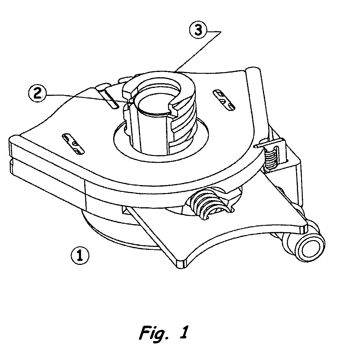
[0041]The inventive nozzle heater 1 is depicted in FIG. 1, in vertical or near vertical attitude. The invention is a novel design for a nozzle heater-cooler 1 that enables tool-less remov...


PUM

PropertyMeasurementUnit
diameteraaaaaaaaaa
diameteraaaaaaaaaa
diameteraaaaaaaaaa

Abstract

A novel nozzle heater design, that facilitates fast thermal response on demand, to achieve rapid reduction in viscosity, allowing fluid to flow through the exit aperture of the nozzle with less pressure, reduced surface tension and elastic behavior at break off. A rapid cool down after a temperature spike alleviates problems associated with prolonged exposure of the fluid at temperature. Prolonged exposure manifests the following problems: volatiles are driven off, premature cross-linking is initiated and fluid in the heated region is subsequently ruined. The fluid path heater is designed to prevent the occurrence of these problems by virtue of the exceptionally fast thermal response rate. This heater design requires no fasteners and is simple to assemble; parts are held in place by inherent geometric relationships and connection to the nozzle hub is tool-less and self-compensating for tolerance variation in the nozzle hub to which it is connected. The heater lowers cost by improving the productivity of the fluid dispensing system on which it is installed.

Description

CROSS REFERENCE TO RELATED APPLICATIONS[0001]Related application Ser. No. 09 / 828,621, Filed Apr. 6, 2001, Now Patent Pending. Related application Ser. No. 10 / 319,906, Filed Dec. 16, 2002, Now Patent Pending. Related application, Ser. No. New, Filed Nov. 11, 2003, Now Patent Pending.FEDERALLY FUNDED RESEARCH[0002]Not ApplicableSEQUENCE LISTING OR PROGRAM[0003]Not ApplicableBACKGROUND OF INVENTION—FIELD OF THE INVENTION[0004]This invention pertains to the field of liquid dispensing equipment. More particularly, it pertains to a novel heater that can be connected to a nozzle hub. The nozzle heater provides a positive locking, tool-less connection to the nozzle hub that is separable and serviceable. A nozzle heater applies heat by conduction through the flat base of the hub via an electrical element and cools convectively along the faces of the hexagonally shaped nozzle hub. It compensates for variations in tolerance of the nozzle hub by changing the elevation of the element to insure i...

Claims


Application Information

Patent Timeline
Patent Type & Authority Patents(United States)
IPC IPC(8): F24H1/10B29C45/27H05B3/42
CPCH05B3/42B29C45/2737
Inventor VERRILLI, BRIAN LEONARD
Owner VERRILLI BRIAN LEONARD
Why Eureka
Try Eureka