Movable belt conveyor system

a belt conveyor and moving technology, applied in conveyors, surface mining, construction, etc., can solve the problem of not substantially compacting the up dump, and achieve the effect of low weigh

Active Publication Date: 2007-03-20
MAN TAKRAF FORDERTECHN
View PDF14 Cites 24 Cited by
  • Summary
  • Abstract
  • Description
  • Claims
  • Application Information

AI Technical Summary

Benefits of technology

[0008]The basic object of the present invention is therefore to provide a movable belt conveyor system that itself has a low weight, with which the dump of a leach pad can be traveled on without the ore piled up being compacted to an extent that is disadvantageous for the application of a subsequent leach process, where the belt conveyor system can be used economically even in case of great lengths.
[0011]The moving of the belt conveyor system into the particular next position is brought about by simultaneous travel with all caterpillar-type moving gears. The caterpillars of the moving gears for the segments as well as for the transfer carriage are arranged exactly in the direction of moving. The caterpillars of the traveling tripper can be pivoted. During the movement of the traveling tripper in the direction of conveying of the movable belt conveyor system, they assume this position in the longitudinal direction of the belt band, but they can be pivoted into the direction of moving for moving the belt conveyor system. The direction of travel of these caterpillars does not need to be pivoted for this directly into the direction of moving; it is already sufficient if the caterpillars are pivoted obliquely into the direction of moving. However, to achieve a uniform moving operation, the velocity of feed of the traveling tripper must be greater than that of the caterpillars of the standard segments, because only one component of the movement leads in the direction of moving of the belt conveyor system. The moving operation takes place with the belt band slackened. After the moving of the entire belt conveyor system, minor corrections of the end position are still carried out, if necessary, due to possible deviations that have developed in the positions of individual segments. Due to the transfer carriage being connected to the tail segment, to the use of a common caterpillar-type moving gear for this, the accommodation of a first belt drive in the tail segment, due to the traveling tripper being designed as an independent device, due to the accommodation of a second belt drive and the belt-tensioning means in the traveling tripper on caterpillars, and due to traveling on the soil next to the leach pad with the common caterpillar-type moving gear of the transfer carriage and of the tail segment, low surface pressure of the belt conveyor system on the dump is achieved. The lightweight design of the standard segments and of the head segment makes possible the use of lightweight driven caterpillar-type moving gears.

Problems solved by technology

Due to the fact that the main sections and the head station comprise only a simple caterpillar-type moving gear and a supporting structure with carrying rollers each, the construction is relatively lightweight; due to the low own weight, the piled-up dump is not compacted substantially by the fact that it is being traveled over during the moving operation.

Method used


Image

  • Movable belt conveyor system
  • Movable belt conveyor system
  • Movable belt conveyor system

Examples


Embodiment Construction

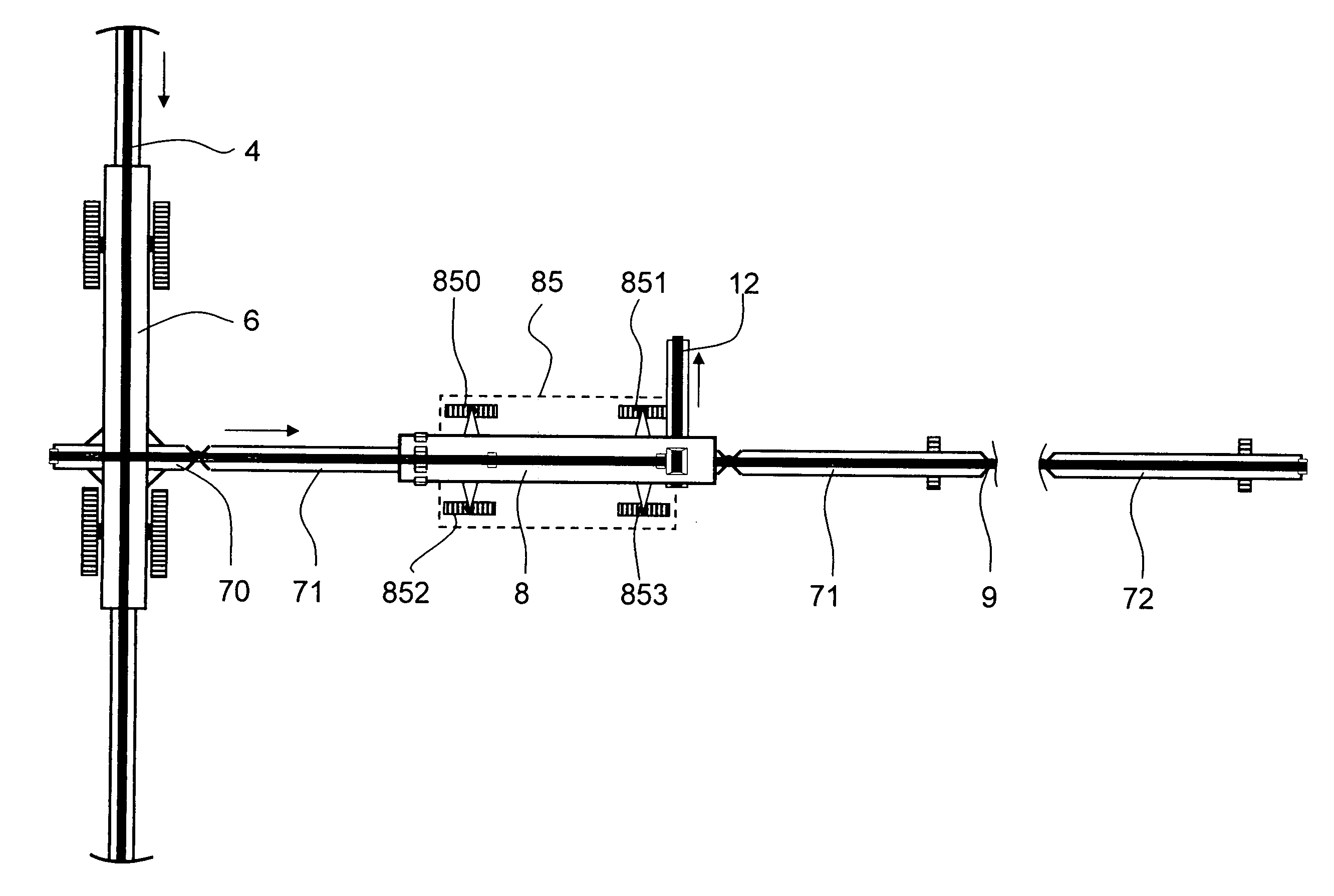
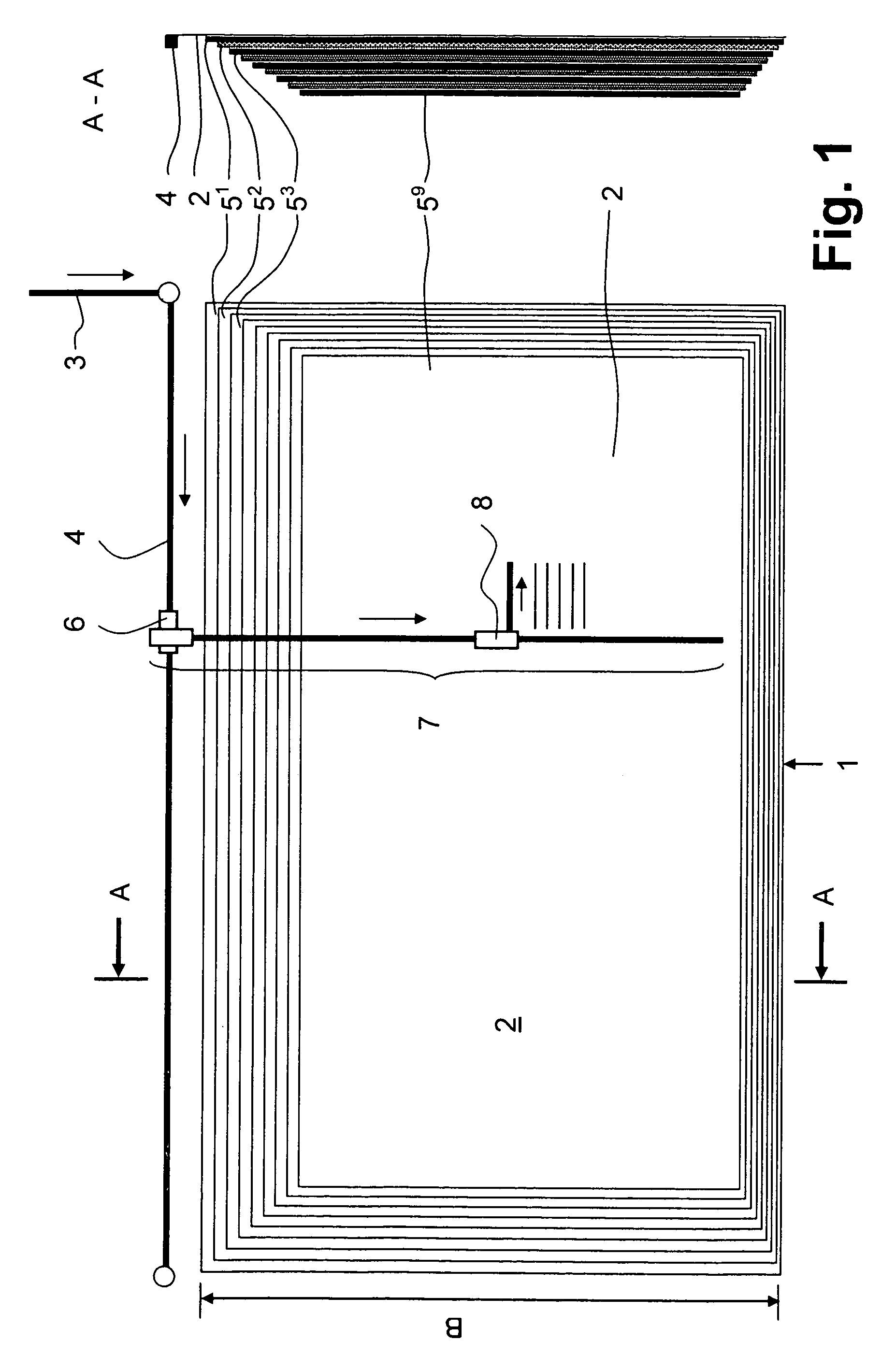
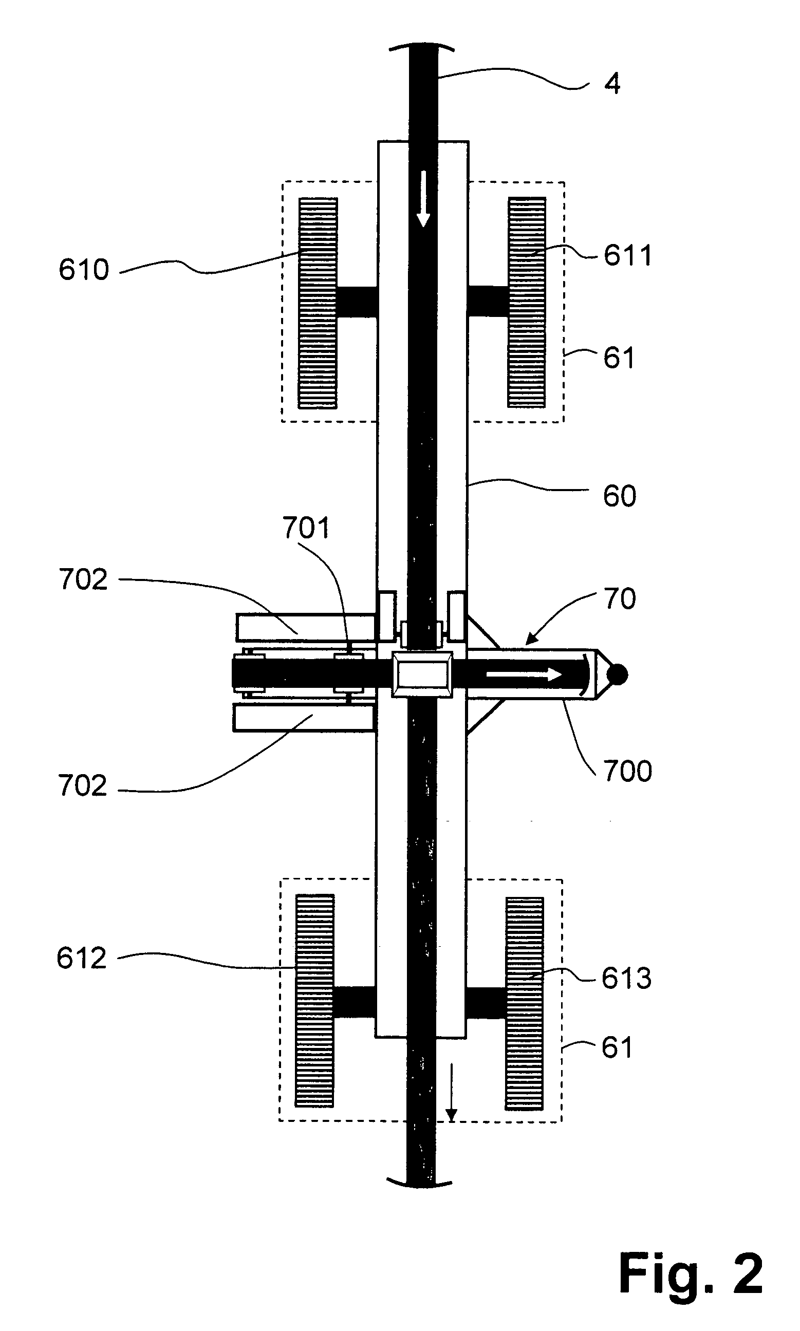
[0022]Referring to the drawings in particular, the leach pad 1 shown in FIG. 1 is intended for extracting ore according to the microbiological ore leaching process. The copper ore is piled up in a plurality of layers 51-n in a width B of one thousand meters and more to form a dump 2. The drawing shows nine layers 51-9. The copper ore is fed to the leach pad 1 by a first intermediate conveyor 3 and a second intermediate conveyor 4 following the former. This second intermediate conveyor 4 is stationary and extends in parallel to the longitudinal side of the leach pad 1 shown at the top in the drawing. The directions of conveying of these conveyors and of the conveyors following these are indicated by arrows. The intermediate conveyor 4 is equipped with a transfer carriage 6 according to FIG. 2. The transfer carriage 6 is displaceable by means of a caterpillar-type moving gear 61, which is arranged under the supporting structure 60 and comprises four steerable individual caterpillars 6...


PUM


Abstract

A movable belt conveyor system for a leach pad for use for sulfidic copper ore, where favorable conditions are to be generated for leaching out the copper by a slight compaction of the ore piled up into a dump for the microbiological leaching technology. The movable belt conveyor system of a length of up to several km is composed of a plurality of smaller belt segments, comprising a tail segment (70), standard segments (711-n) and a head segment (72), as well as a traveling tripper (8). To prevent the loading by these individual components from being excessively compacted by the weight of the device during multiple travel over the dump during the moving process, the belt drives with the driving drum are accommodated in the tail element (70), which is supported on the soil next to the leach pad. In addition, the traveling tripper (8) is designed as an independent unit with the belt drums, additional belt drives and the belt-tensioning means, which unit is autarchically displaceable on a caterpillar-type moving gear (85) of its own. Due to the moving of the belt on the caterpillar-type moving gears of the standard segments (711-n), on the head segment (72) and on the traveling tripper (8) as well as due to the absorption of the weight of the tail segment (70) by the transfer carriage (6), the surface pressure acting locally on the dump is reduced and the compaction of the ore on the dump due to being traveled over by the belt conveyor system remains low. Traveling over with a moving device, which frequently happens with the use of a moving caterpillar, is eliminated.

Description

CROSS REFERENCE TO RELATED APPLICATIONS[0001]This application claims the benefit of priority under 35 U.S.C. § 119 of German Application Number DE 10 2005 039 067.6 filed Aug. 18, 2005, the entire contents of which are incorporated herein by reference.FIELD OF THE INVENTION[0002]The present invention pertains to a movable belt conveyor system that is especially suitable for use with sulfidic copper ore, where favorable conditions are to be created for leaching out the copper by a slight compaction of the ore piled up in a dump allowing for microbiological leaching technology to act.BACKGROUND OF THE INVENTION[0003]It is known that movable belt conveyor systems can be used for leaching oxidic copper ores by acid. Compaction by moving the belt conveyor system with moving caterpillars (endless tracks) is less critical here. In general, the conveying system for piling up a leach pad comprises a plurality of feed belts, a movable tipping belt and a stacking system with traveling trippers...

Claims


Application Information

Patent Timeline
Patent Type & Authority Patents(United States)
IPC IPC(8): B65G65/02
CPCB65G41/008B65G47/95E21C41/32E02F5/26E02F7/02B65G65/28B65G2201/045
Inventor KAHRGER, RAINERHOFFMANN, DIETER
Owner MAN TAKRAF FORDERTECHN
Why Eureka
Try Eureka