Fire-fighting monitor with remote control

a fire-fighting monitor and remote control technology, applied in mechanical equipment, transportation and packaging, liquid transfer devices, etc., can solve the problems of wasting water, difficult to achieve accurate aiming of the nozzle and hence the water stream, and the firefighter may run the risk of entering the collapse zone of the building or getting too close to hazardous materials, etc., to achieve the effect of reducing water damage, saving water, and reducing the risk of falling o

Inactive Publication Date: 2007-03-20
ELKHART BRASS MFG
View PDF27 Cites 41 Cited by
  • Summary
  • Abstract
  • Description
  • Claims
  • Application Information

AI Technical Summary

Benefits of technology

[0006]Accordingly, the present invention provides a monitor that can be remotely controlled and, further, controlled in a manner to achieve greater accuracy in the positioning of the nozzle and, hence, the direction of water stream from the nozzle to conserve water, reduce water damage, and hasten fire suppression.
[0023]Accordingly, as would be understood, the monitor of the present invention provides a remote controlled monitor than can be configured as a portable monitor or a deck gun monitor on a truck. The position of the nozzle mounted to the monitor is remotely controlled so that the operator of the monitor can stay clear of the collapse zone of the building and stay at a safe distance from any hazardous materials. Further, the positioning of the nozzle can be achieved with greater accuracy, which reduces waste, water damage, and hastens fire suppression.

Problems solved by technology

However, when manually operating a monitor, the firefighter may run the risk of entering the collapse zone of the building or getting too close to hazardous materials.
Further, given the operating position of the firefighter, either immediately behind or adjacent to the monitor, accurate aiming of the nozzle and, hence the water stream, is often difficult to achieve.
Without accurate stream placement, water can be wasted.

Method used


Image

  • Fire-fighting monitor with remote control
  • Fire-fighting monitor with remote control
  • Fire-fighting monitor with remote control

Examples


Embodiment Construction

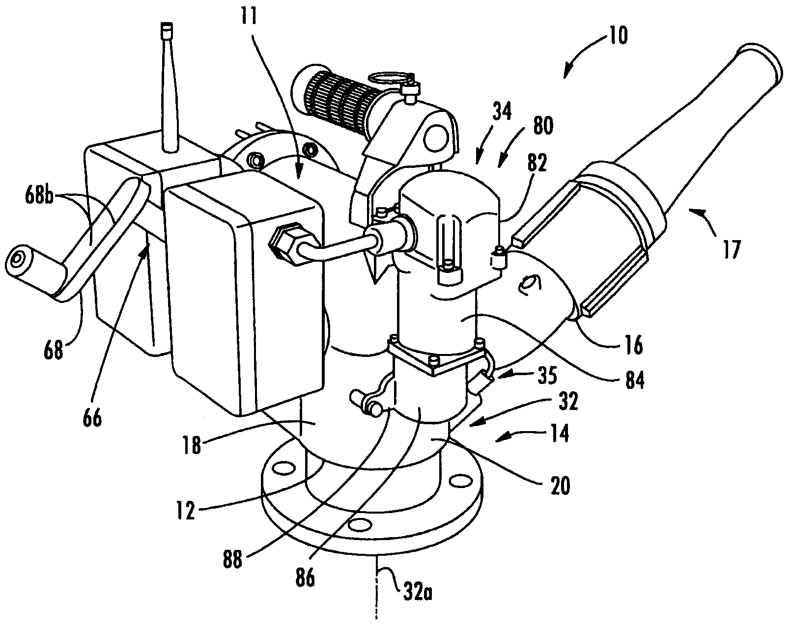
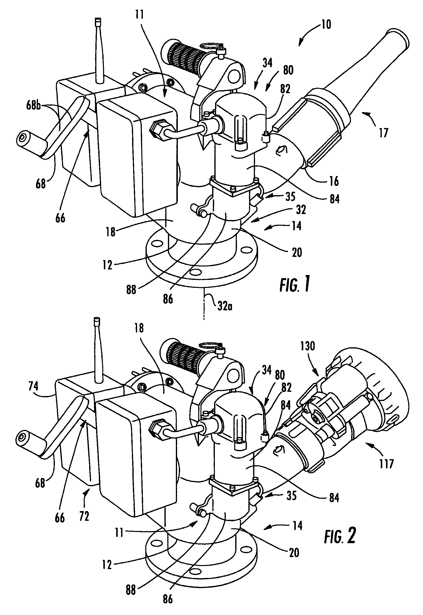
[0056]Referring to FIG. 1, the numeral 10 generally designates a monitor of the present invention. As will be more fully described below, monitor 10 is adapted to be remotely controlled so that the monitor can be positioned closer to a fire while allowing the operator of the monitor to stay out of the collapse zone of a building and away from hazardous materials that may be present at the fire scene and, further, to achieve greater accuracy in the positioning of the nozzle that is mounted to the monitor. In addition, monitor 10 is configured so that it can be mounted to a fixed base (14) or portable base (214), while still retaining its remotely controlled function on either base and, further, so that it can be readily transferred between the bases.

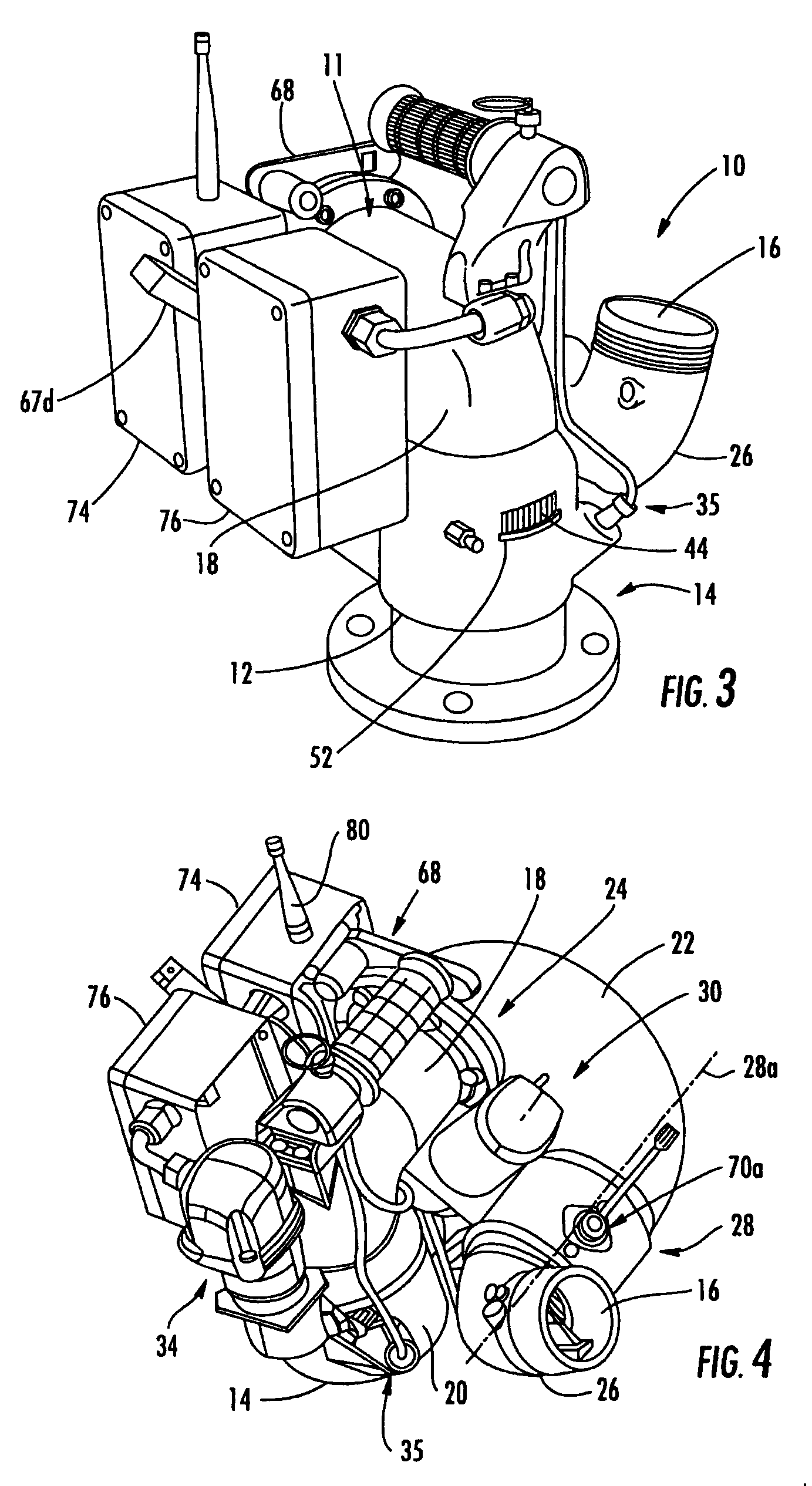
[0057]Referring to FIGS. 1–4, monitor 10 includes a housing 11 with an inlet 12, which is adapted to connect to a fixed deck gun base 14 (FIG. 1) or a portable base 214 (FIG. 23), and an outlet 16 which is adapted for mounting a nozzle 17...


PUM


Abstract

A fire-fighting monitor for directing the flow of fluid from a fluid source includes a base, which is adapted to connect to a fluid source, and a monitor housing. The monitor housing includes an inlet and an outlet, with the inlet releasably mounted on the base and for receiving fluid through the base. The outlet is in fluid communication with the inlet for discharging fluid from the housing. A rotatable connection is provided between the inlet and the base. The inlet is rotatable about the base at the rotatable connection about a first axis. A drive mechanism is associated with the rotatable connection for rotating the inlet about the base at the rotatable connection. The monitor further includes a control system for selectively actuating the drive mechanism and includes a receiver for receiving an input signal from a transmitter remote from the monitor. The control system actuates the drive mechanism in response to the receiver receiving the input signal.

Description

[0001]The present application is a continuation-in-part of application entitled RADIO CONTROLLED LIQUID MONITOR, Ser. No. 10 / 405,372, filed Apr. 2, 2003 now U.S. Pat. No. 6,994,282, which is incorporated herein in its entirety.TECHNICAL FIELD AND BACKGROUND OF THE INVENTION[0002]The present invention is directed to a fire-fighting monitor and, more specifically, to a remote controlled fire-fighting monitor that can be used as a deck gun or as a portable monitor.[0003]Portable fire-fighting monitors are specialized fire-fighting equipment that are used in conjunction with a nozzle, such as a fixed nozzle or adjustable nozzle, such as a stream shaper, to direct water at a high flow rate. Portable monitors are typically interchangeable between a deck-gun mount or base on a fire truck and a portable mount or base, such as described in U.S. Pat. No. 4,674,686, which is incorporated by reference herein in its entirety. Other portable monitors incorporate a base into the monitor body itsel...

Claims


Application Information

Patent Timeline
Patent Type & Authority Patents(United States)
IPC IPC(8): B05B15/08B05B15/68A62C31/24
CPCA62C31/24Y10S285/92A62C27/00
Inventor TRAPP, JAMES M
Owner ELKHART BRASS MFG
Why Eureka
Try Eureka