
Porous membranes for use with implantable devices

a technology of porous membranes and implantable devices, which is applied in the field of biointerface membranes, can solve the problems of local inflammation response, limiting the function of implanted devices, and poor transport of molecules across the device-tissue interface,

Inactive Publication Date: 2007-03-20
DEXCOM INC
View PDF325 Cites 1206 Cited by
  • Summary
  • Abstract
  • Description
  • Claims
  • Application Information

AI Technical Summary

Benefits of technology

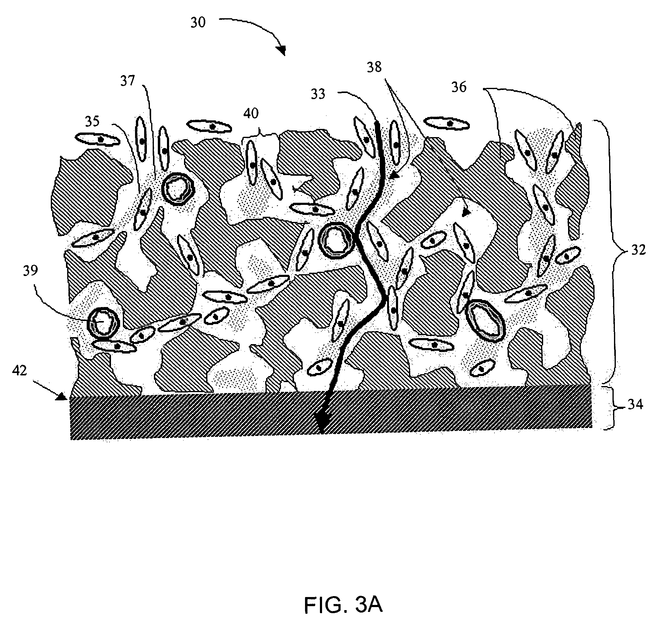
The patent describes a membrane for implantation in soft tissue that supports tissue ingrowth and interferes with barrier cell layer formation. The membrane has two domains: a first domain that supports tissue ingrowth and interferes with barrier cell layer formation, and a second domain that allows the passage of analytes. The membrane has interconnected cavities and a solid portion, with a substantial number of the cavities being greater than or equal to about 90 microns in at least one dimension. The membrane is suitable for use in an implantable device and can be made of materials such as polyurethane or polyvinylpyrrolidone. The technical effect of the membrane is to provide a barrier to cellular attachment and facilitate the transport of analytes across the membrane.

Problems solved by technology

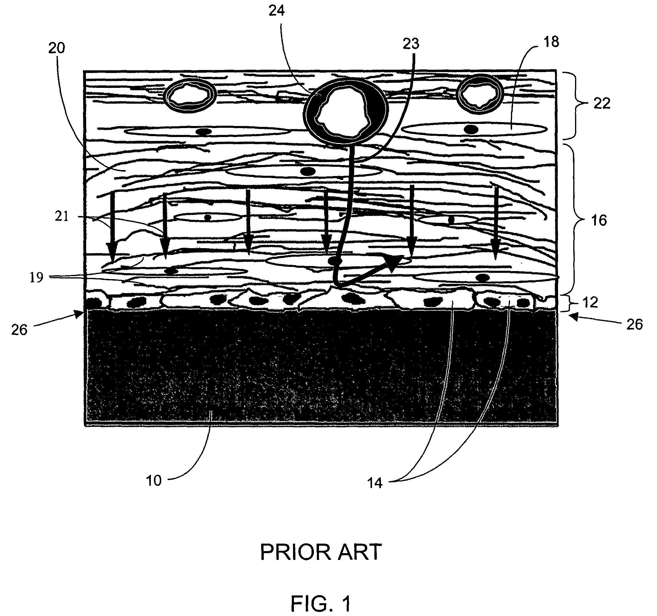
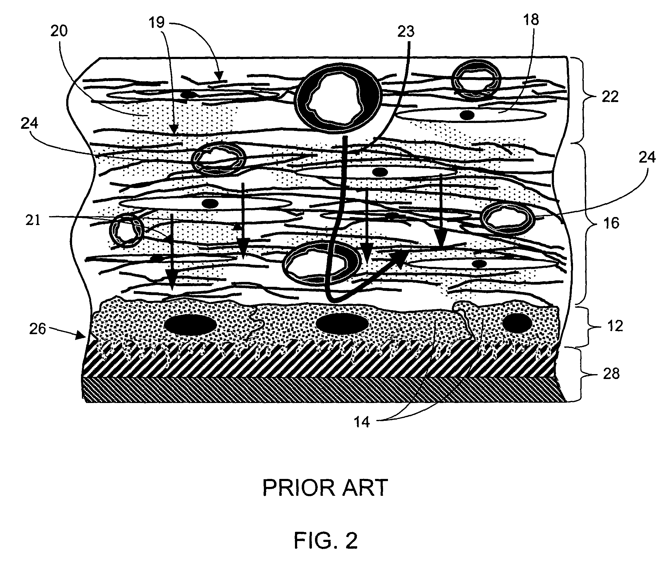
A disadvantage of conventional biointerface membranes is that they often stimulate a local inflammatory response, called the foreign body response (FBR), which has long been recognized as limiting the function of implanted devices that require solute transport.
This has led to widely supported speculation that poor transport of molecules across the device-tissue interface 26 is due to a lack of vascularization near the interface.
Previous efforts to overcome this problem have been aimed at increasing local vascularization at the device-tissue interface, but have achieved only limited success.
For example, when applied to an implantable glucose sensor, both glucose and its phosphorylated form do not readily transit the cell membrane.
However, it has been observed that once the monolayer of cells (barrier cell layer) is established adjacent to a membrane, increasing angiogenesis is not sufficient to increase transport of molecules such as glucose and oxygen across the device-tissue interface 26.

Method used


Image

  • Porous membranes for use with implantable devices
  • Porous membranes for use with implantable devices
  • Porous membranes for use with implantable devices

Examples


Embodiment Construction

[0275]The following description and examples illustrate some exemplary embodiments of the disclosed invention in detail. Those of skill in the art will recognize that there are numerous variations and modifications of this invention that are encompassed by its scope. Accordingly, the description of a certain exemplary embodiment should not be deemed to limit the scope of the present invention.

Definitions

[0276]In order to facilitate an understanding of the preferred embodiments, a number of terms are defined below.

[0277]The term “biointerface membrane” as used herein is a broad term and is used in its ordinary sense, including, without limitation, a permeable membrane that functions as a device-tissue interface comprised of two or more domains. In some embodiments, the biointerface membrane is composed of two domains. The first domain supports tissue ingrowth, interferes with barrier cell layer formation, and includes an open cell configuration having cavities and a solid portion. Th...


PUM

PropertyMeasurementUnit
wt. %aaaaaaaaaa
particle sizeaaaaaaaaaa

Abstract

A membrane for implantation in soft tissue comprising a first domain that supports tissue ingrowth, disrupts contractile forces typically found in a foreign body response, encourages vascularity, and interferes with barrier cell layer formation, and a second domain that is resistant to cellular attachment, is impermeable to cells and cell processes, and allows the passage of analytes. The membrane allows for long-term analyte transport in vivo and is suitable for use as a biointerface for implantable analyte sensors, cell transplantation devices, drug delivery devices, and / or electrical signal delivering or measuring devices. The membrane architecture, including cavity size, depth, and interconnectivity, provide long-term robust functionality of the membrane in vivo.

Description

RELATED APPLICATION[0001]This application claims the benefit of U.S. Provisional Application No. 60 / 472,673 filed May 21, 2003.FIELD OF THE INVENTION[0002]The preferred embodiments relate generally to biointerface membranes that can be utilized with implantable devices such as devices for the detection of analyte concentrations in a biological sample (e.g., a body), cell transplantation devices, drug delivery devices, electrical signal delivering or measuring devices, and / or combinations thereof.BACKGROUND OF THE INVENTION[0003]Some medical devices, including implanted analyte sensors, drug delivery devices and cell transplantation devices require close vascularization and transport of solutes across the device-tissue interface for proper function. These devices generally include a biointerface membrane, which encases the device or a portion of the device to prevent access by host inflammatory cells, immune cells, or soluble factors to sensitive regions of the device.[0004]A disadva...

Claims


Application Information

Patent Timeline
Patent Type & Authority Patents(United States)
IPC IPC(8): A61F2/02A61L31/10A61L31/14A61L31/16
CPCA61L31/10A61L31/146A61L31/14
Inventor BRAUKER, JAMES H.CARR-BRENDEL, VICTORIATAPSAK, MARK A.
Owner DEXCOM INC
Learn More