Method for improving crack resistance in fiber-metal-laminate structures

a technology of laminate structure and fiber metal, which is applied in the direction of special ornamental structure, transportation and packaging, chemical instruments and processes, etc., can solve the problems of reducing the and reducing the service life of fatigue at an existing stress level, so as to reduce the disruption and cost, prolong the service life, and delay the onset of crack initiation

Inactive Publication Date: 2007-03-20
THE BOEING CO
View PDF20 Cites 12 Cited by
  • Summary
  • Abstract
  • Description
  • Claims
  • Application Information

AI Technical Summary

Benefits of technology

[0008]The present invention delays the onset of crack initiation in fiber-metal-laminate structures by subjecting outer metallic laminate layers to residual compressive stresses and subjecting fiber laminate substrate layers to residual tensile stresses. If desired, the present invention can advantageously be used in selected regions of a structure, such as without limitation a structure with complex geometry. Or, if desired, the present invention can be used in an entire structure, regardless of geometry of the structure. As a result, the present invention avoids disruptions and costs that are incurred by currently-known techniques by removing a part from a continuous line process for treatment to increase fatigue life.

Problems solved by technology

However, the generally thin nature of the laminate layers creates difficulties in maintaining the integrity of the outer laminate layer.
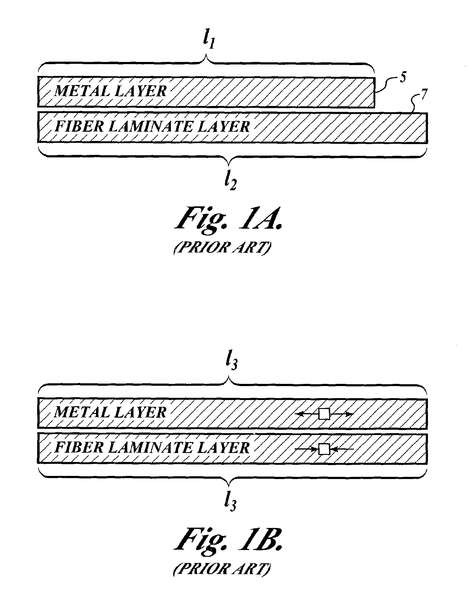
Thus, fatigue life at an existing stress level is shortened when the outer metal laminate layer is subject to residual tension stresses.
However, such an approach can become costly.
However, this process is employable only in sheet-type laminate structures and not with a laminate structure having a more complex geometry.
Therefore, there exists an unmet need in the art for decreasing the onset of crack initiation of fiber-metal-laminate materials of any geometry without adding structure or pre-stressing entire laminate structures.

Method used


Image

  • Method for improving crack resistance in fiber-metal-laminate structures
  • Method for improving crack resistance in fiber-metal-laminate structures
  • Method for improving crack resistance in fiber-metal-laminate structures

Examples


Embodiment Construction

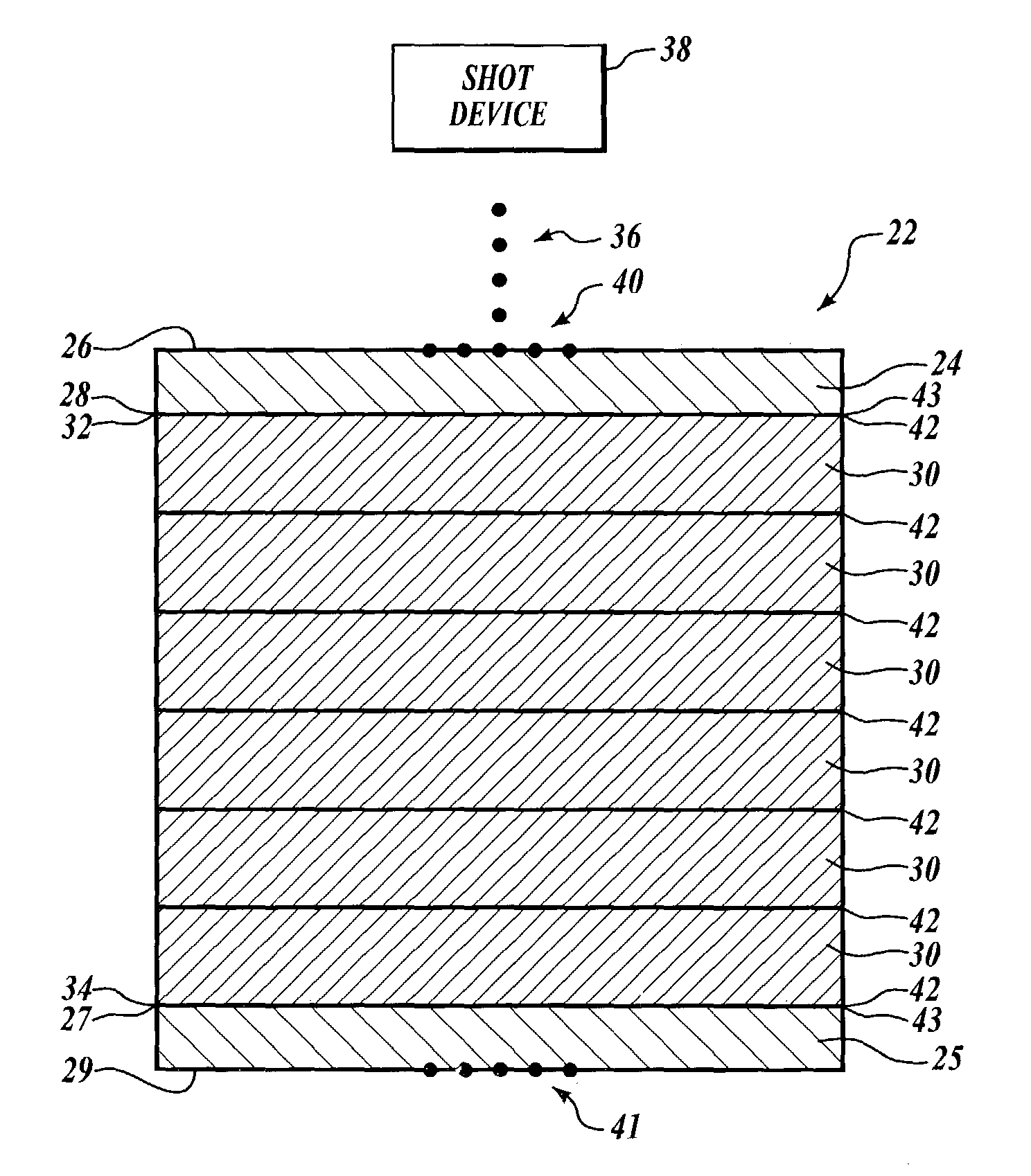
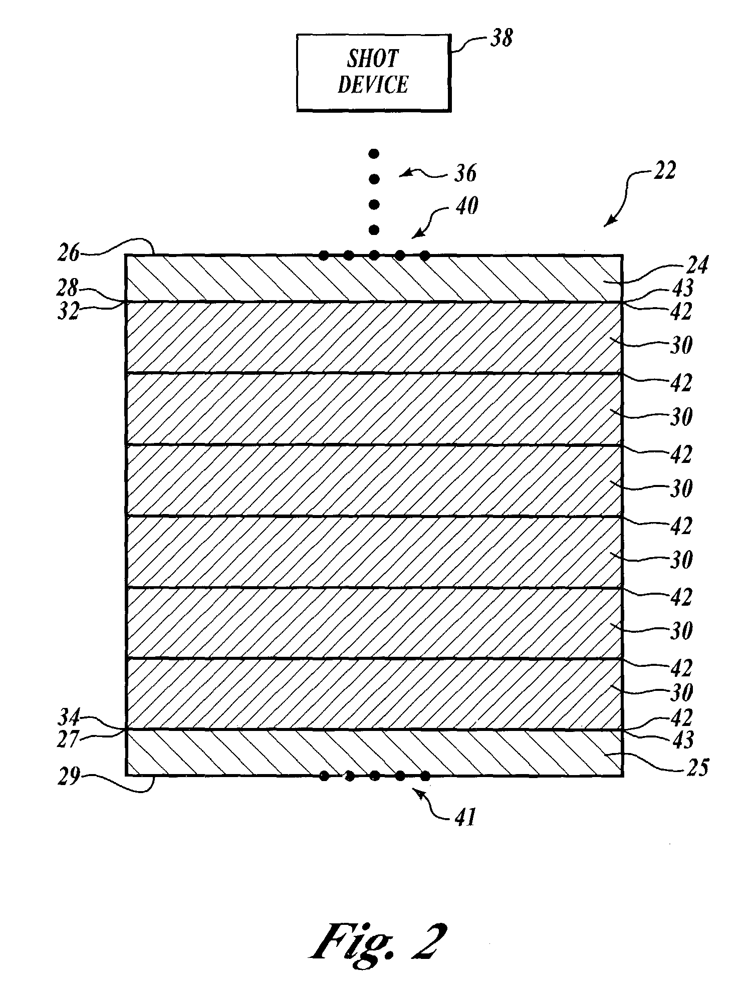
[0015]The present invention provides a method for delaying onset of crack initiation in fiber-metal-laminate structures and a fiber-metal-laminate structure that has increased resistance to crack initiation regardless of complexity of the structure's geometry. Advantageously, the present invention causes outer metallic layers of the structure to be subjected to residual compression stresses and the fiber substrate layers to be subjected to residual tensile stresses. In one present embodiment, peening the outer metallic layers induces the residual stresses in the outer metallic layers and the substrate layers. By way of overview and with reference to FIG. 2, one non-limiting embodiment of the present invention provides a fiber-metal-laminate structure 22 that includes a plurality of fiber laminate substrate layers 30 that define a first surface 32 and a second surface 34. A first outer metallic laminate layer 24 has a third surface 26 and a fourth surface 28 that is bonded to the fir...


PUM

PropertyMeasurementUnit
thicknessesaaaaaaaaaa
thicknessaaaaaaaaaa

Abstract

A method is provided for altering residual stresses in a fiber-metal-laminate structure. At least a first fiber laminate substrate layer having first and second surfaces is provided. At least a first outer metallic laminate layer having third and fourth surfaces is provided, and the first and fourth surface is provided, and the first and fourth surfaces are bonded together. The third surface is peened, such that the at least first fiber laminate substrate layer is subjected to residual tensile stresses and the at least first outer metallic laminate layer is subjected to residual compression stresses. Peening defines a peened region that extends from the third surface into the at least first outer metallic laminate layer a finite distance that is closer to the third surface than the fourth surface.

Description

FIELD OF THE INVENTION[0001]This invention relates generally to methods for delaying onset of crack initiation and, more specifically, to methods for delaying onset of crack initiation in laminate structures.BACKGROUND OF THE INVENTION[0002]Fiber-metal-laminate structures are becoming an increasingly popular material choice where strength or weight, or both strength and weight, are taken into consideration. For example, fiber-metal-laminates are used in the aircraft and automotive industries as lightweight and high-strength alternatives to non-laminate structures.[0003]Generally, a laminate structure having an outer laminate layer that is resistant to failure is preferred as an exterior layer. This is because the outer laminate layer protects the inner laminate layers and the bond layers from potentially harmful elements that may cause laminate structure failure, as well as providing an aesthetically pleasing surface. However, the generally thin nature of the laminate layers creates...

Claims


Application Information

Patent Timeline
Patent Type & Authority Patents(United States)
IPC IPC(8): B24B1/00B32B15/14C21D7/06
CPCB32B15/14C21D7/06Y10T156/1046Y10T156/1039Y10T428/12993C21D2251/02B32B7/12B32B2311/24B32B2311/18B32B2262/106
Inventor WESTRE, WILLARD N.MICONA, LEANNA M.VAN BEEK, EARL E.
Owner THE BOEING CO
Why Eureka
Try Eureka