Adjustable gas spring suspension system

a technology of gas springs and suspension systems, which is applied in the direction of shock absorbers, steering devices, cycle equipments, etc., can solve the problems of unnecessarily heavy, cumbersome riding of forks with longer travel, and increased travel requirements, so as to reduce travel, softer spring rate, and the effect of reducing travel

Active Publication Date: 2007-03-27
SRAM CORPORATION
View PDF5 Cites 51 Cited by
  • Summary
  • Abstract
  • Description
  • Claims
  • Application Information

AI Technical Summary

Benefits of technology

[0006]The adjustment assembly, by adjusting the position of the shaft within the pressure chamber and the position of the piston assembly along the piston tube, also adjusts the spring rate for a new travel setting. Typically, for a shorter travel setting, a stiffer or higher spring rate is desired, while for a longer travel setting, a softer spring rate is desired. When the adjustment assembly is adjusted to decrease the travel, the shaft further enters the pressure chamber and the piston assembly is displaced or positioned along the piston tube, both displacements decreasing the volume of the pressure chamber to increase the spring rate. Likewise, when the adjustment assembly is adjusted to increase the travel, the shaft is further withdrawn from the pressure chamber and the piston assembly is displaced or positioned in an opposite direction, both displacements increasing the volume of the pressure chamber to decrease the spring rate. Thus, the present invention provides a desirable spring rate at any travel setting without having to separately adjust the gas pressure, allowing riders to change the travel of their forks while riding—on the fly—without having to externally add or remove gas from the pressure chamber. Nonetheless, a valve, attached to the frame and in communication with the pressure chamber, may be included to adjust pressure settings in the pressure chamber as needed.

Problems solved by technology

However, as riders began to traverse rougher terrain at higher speeds, a greater amount of travel was needed to absorb the higher riding forces.
However, forks with longer travel may be cumbersome to ride, especially when riding uphill, due to the raised front end geometry and the resulting softer spring rate.
Another problem with existing bicycle suspension forks is that they are unnecessarily heavy.
Besides increasing the overall weight of the bicycle, the weight of the fork affects the handling of the bicycle.
Bicycle suspension systems with adjustable travel have been designed, however, most use a helical compression spring that adds unnecessary weight.
One problem with existing gas spring forks is that the rider must perform a two-step process to adjust the travel.

Method used


Image

  • Adjustable gas spring suspension system
  • Adjustable gas spring suspension system
  • Adjustable gas spring suspension system

Examples


Embodiment Construction

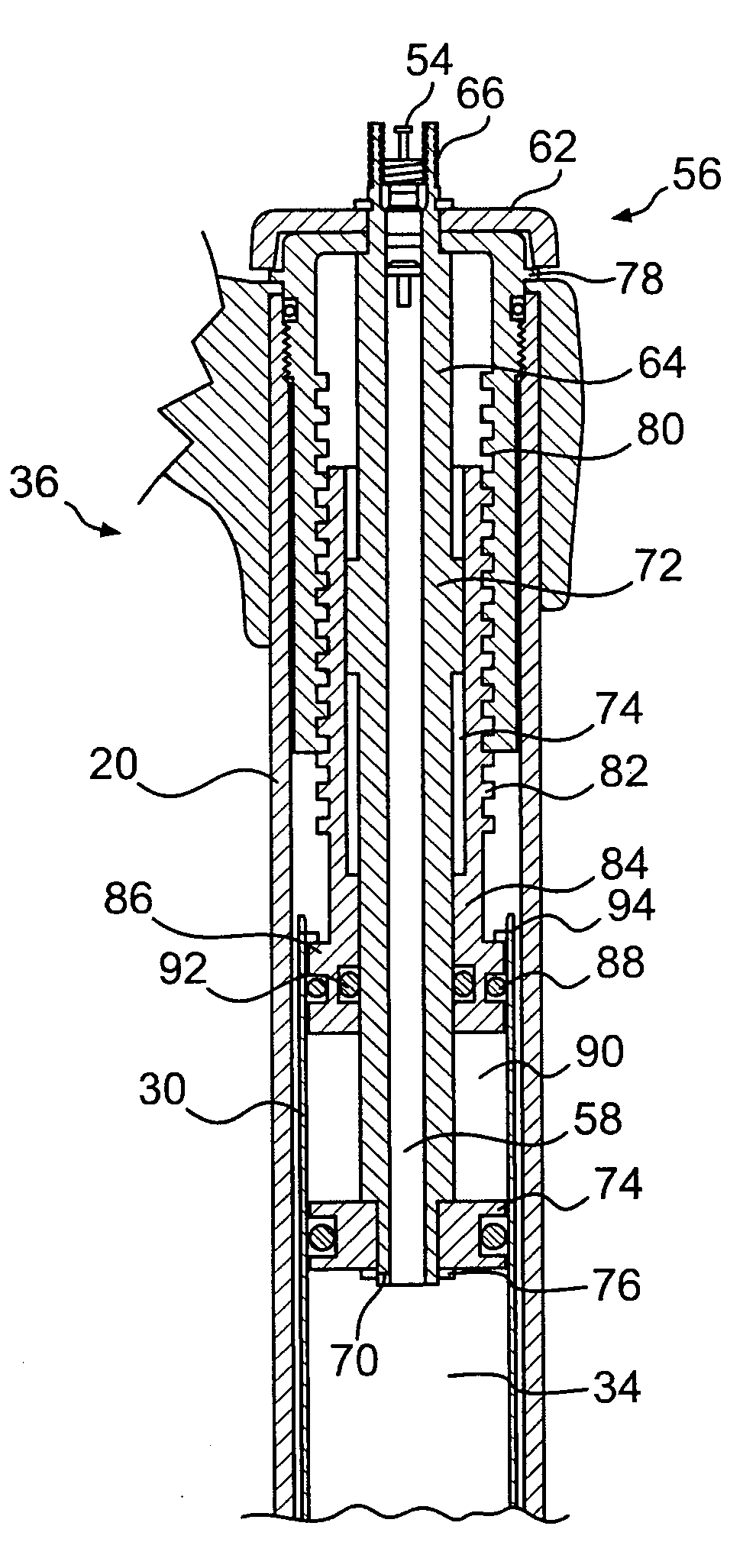
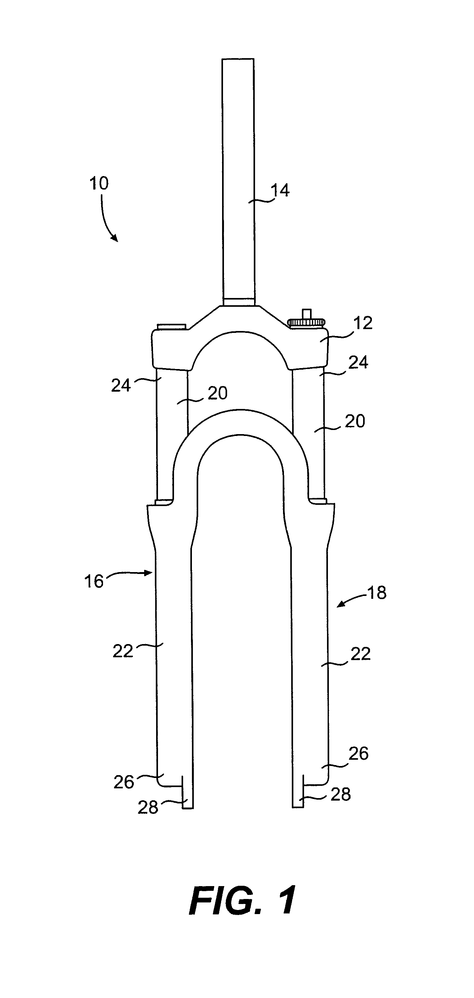
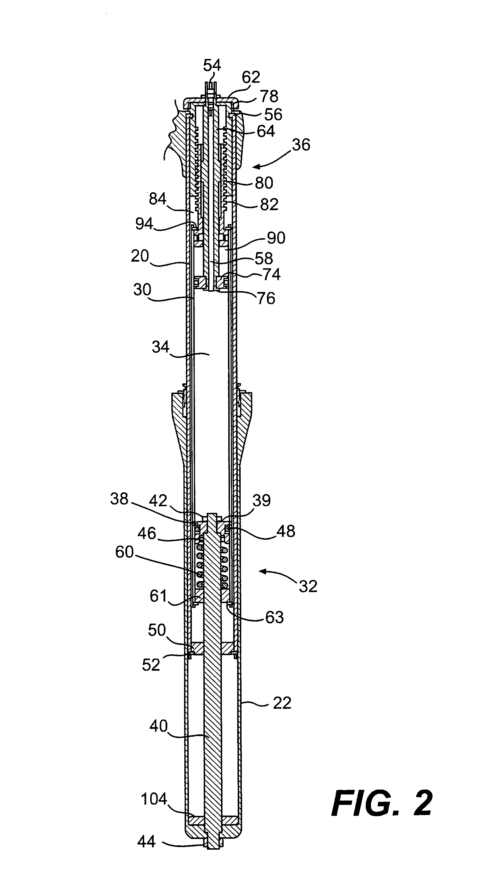
[0021]FIGS. 1–9 illustrate a bicycle front suspension fork 10 that includes a gas spring suspension system 11 in accordance with one embodiment of the present invention. However, a gas spring suspension system according to the present invention may be used in a rear shock, a seat post, or at other locations on a bicycle frame. Likewise, the gas spring suspension of the present invention may be used on motorcycles as well as other handlebar-steered vehicles. Looking to FIG. 1, the bicycle front suspension fork 10 includes a crown 12 that is connected to a steerer tube 14, a first leg 16 and a second leg 18. Each of the legs 16, 18 include an upper tube 20 and a lower tube 22. Although the upper tubes 20 are shown as inner tubes slidable within the lower outer tubes 22, it will be appreciated that the lower tubes may alternatively be reconfigured as inner tubes slidable within the reconfigured outer tubes. Additionally, although the tubes 20, 22 are shown to have substantially circula...


PUM


Abstract

A gas spring suspension system that adjusts the spring rate as the travel is adjusted. The suspension system includes a frame, a pressure chamber, a compression piston assembly, an adjustment assembly, a piston tube, and a shaft. The piston tube is operatively connected to the adjustment assembly and the compression piston assembly, and the compression piston assembly is configured to slidably displace along the piston tube to change the pressure in the pressure chamber. The adjustment assembly is associated with the frame and is operable to axially position the piston tube and, in turn the compression piston assembly, relative to the frame to adjust the travel of the suspension system. The shaft is configured to be variably positionable within the pressure chamber in response to axial displacement of the piston tube and the compression piston assembly by the adjustment assembly, the variable positioning of the shaft within the pressure chamber changing the pressure therein.

Description

BACKGROUND OF THE INVENTION[0001]The present invention relates to gas spring suspension systems and more particularly to a gas spring suspension system that adjusts the spring rate as the travel is adjusted.[0002]Bicycles include suspension systems to cushion the rider from irregularities in the terrain. Bicycle suspension systems are typically located at the front and rear forks, the seat tube, or at other bicycle frame locations. A typical front suspension fork includes two legs, each leg having inner and outer telescoping tubes. At least one leg includes a resilient member for biasing the inner and outer tubes apart from each other and for absorbing compressive forces applied to the fork. The resilient member may be a coil spring, an elastomer spring, a gas spring or the like. The maximum amount the tubes may compress relative to each other is commonly referred to as the travel of the fork. Early suspension forks were capable of about 50 mm of travel. However, as riders began to ...

Claims


Application Information

Patent Timeline
Patent Type & Authority Patents(United States)
IPC IPC(8): F16F5/00B62K25/08F16F9/02
CPCF16F9/0245B62K25/08
Inventor JORDAN, BRIAN T.SHIPMAN, CHRISTOPHER A.CHEEVER, JOHN D.OLDS, STEVEN J.
Owner SRAM CORPORATION
Why Eureka
Try Eureka