Apparatus for a fire-rated duct

a technology of ducts and apparatus, applied in the field of duct systems, can solve the problems of increased fabrication costs, less economical than many other competing products, and high cost of frd-b>1/b> duct systems, and achieve the effect of preventing the passage of heat and preventing fire from jumping

Inactive Publication Date: 2007-03-27
DURASYST BARRIERS
View PDF53 Cites 47 Cited by
  • Summary
  • Abstract
  • Description
  • Claims
  • Application Information

AI Technical Summary

Benefits of technology

[0010]The present invention provides a fire-resistant duct system that prevents the passage of heat from one fire compartment to another through the components of the duct system. By preventing the passage of heat, the fire is prevented from jumping from one fire compartment to another by igniting combustible in the non fire involved compartment.

Problems solved by technology

While effective in a fire, the FRD-1 duct system is expensive due to the labour involved in the manufacture of the product and its increased weight due to the thickness of steel required to support the panels make it less economical than many of the other competing products.
While effective in use where fire temperatures could reach high levels in a relatively short time, the additional weight of the inner liner and insulation as well as the additional fabrication costs resulting from the addition of the inner assemblies makes this system only practical for special applications.
Perceived shortcomings of these systems include: (a) the need for multiple skilled tradesmen to install the finished system that can result in project scheduling issues; (b) ease of damage to the aluminum scrim outer coating that could result in a reduced fire resistance level and lead to the spread of ceramic fibers throughout the building; (c) the inability to ensure the system is correctly installed as per the factory guidelines; improper installation could result in a system offering little or no protection; (d) the thickness of the insulation wrap material results in an increased outer dimension for the duct work.
The drawback of such board systems include: (a) as with the insulation wraps, there is the need for multiple tradesmen to install the finished system which can result in project scheduling issues; (b) the fire-resistant cladding boards are subject to being damaged from impacts during or after installation; (c) the fire-resistant cladding boards are also susceptible to damage when exposed to high levels of moisture; (d) it is also not always possible to ensure installation of the fire-resistant cladding as per the manufacturers guidelines; and improper installation may result in a system offering little or no protection.

Method used


Image

  • Apparatus for a fire-rated duct
  • Apparatus for a fire-rated duct
  • Apparatus for a fire-rated duct

Examples


Embodiment Construction

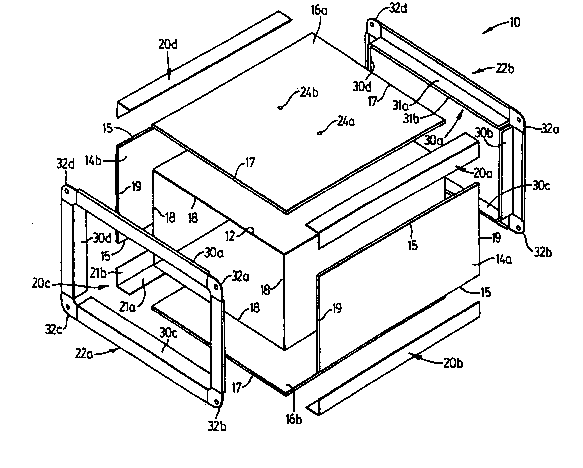
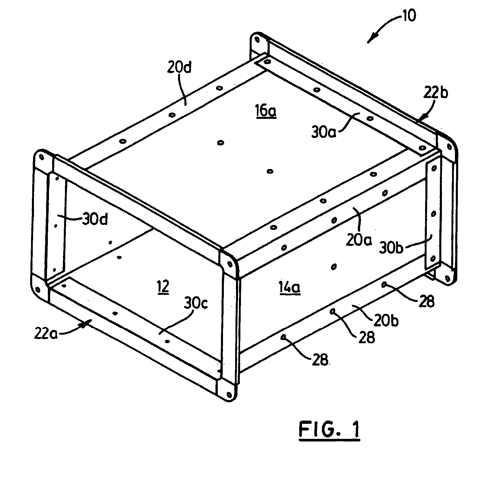
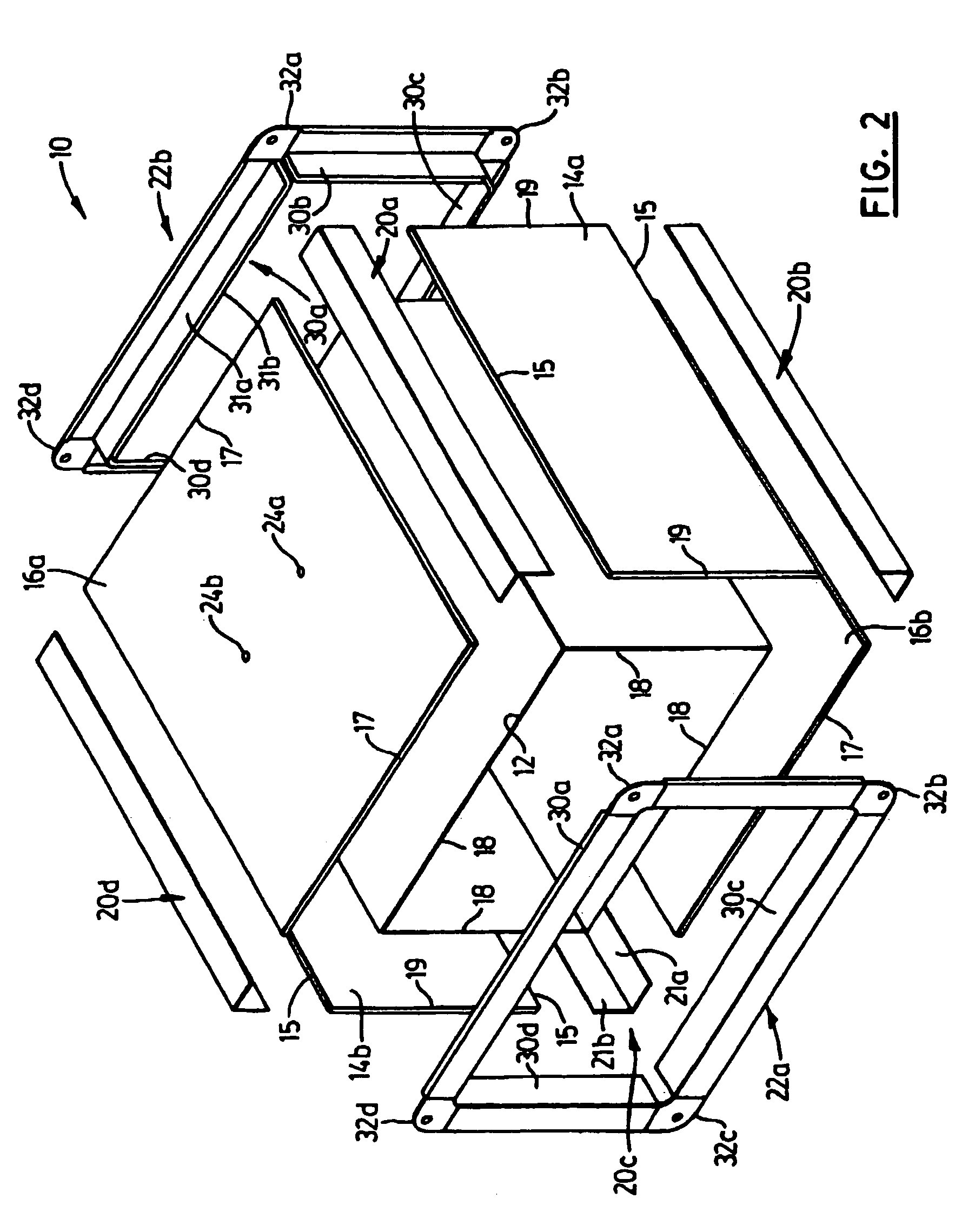
[0023]Reference is first made to FIGS. 1 to 4, which show a fire-rated duct system in accordance with the present invention and indicated generally by reference 10. In the drawings, like references indicate like elements or features.

[0024]While the fire-rated duct system 10 is described in the context of an HVAC application, it is to be appreciated that the duct system 10 has wider applicability. The duct system 10 is suitable for other applications including encasing or surrounding electrical wiring and wiring runs, plumbing runs, communication lines and data networks, in addition to smoke evacuation.

[0025]As shown, the fire-rated duct system 10 comprises an inner duct liner 12, fire-resistant side panels 14 (shown individually as 14a and 14b), and a fire-resistant top-bottom panel 16 (indicated individually by reference 16a and 16b). The fire-rated duct system 10 also includes corner angle sections 20 (indicated individually by references 20a, 20b, 20c and 20d), and end connector ...


PUM


Abstract

A duct system comprising duct sections which are factory manufactured and field modifiable. The field modifiable duct system comprises fire resistant materials and is fire-rated. The duct sections when assembled create a continuous conduit that allows air to flow from a fresh air source to the required area of the building.

Description

FIELD OF THE INVENTION[0001]The present invention relates to ducting systems, and more particularly to a fire-rated duct.BACKGROUND OF THE INVENTION[0002]Large buildings must provide a safe path of egress for the occupants in case of fire. To achieve this, floors and walls are fire rated to prevent fire from traveling from one compartment or floor to another. To allow persons to escape the building, fresh air is also essential to prevent the occupants from being overcome by smoke while attempting to exit the building. To achieve this the ducts that are designed to deliver fresh air during a fire must be constructed so that even if the duct passes through a fire compartment that is fully engulfed in fire, the construction of the duct will withstand the effects of the fire and permit the continuous flow of fresh air to the persons evacuating the building.[0003]An example of the application of fire rated duct system is a stair pressurization system which is typically mandated by buildi...

Claims


Application Information

Patent Timeline
Patent Type & Authority Patents(United States)
IPC IPC(8): F16L25/00F16L23/00F16L9/22A62C2/06A62C3/00F16L23/14F16L59/14F24F13/02
CPCF16L23/14F16L25/0009F24F13/0209F16L59/145A62C2/06Y10S138/04F24F2221/30
Inventor DUFFY, WILLIAM CHRISTOPHER
Owner DURASYST BARRIERS
Why Eureka
Try Eureka