
Prismatic retroreflective article and method

a retroreflective article and article technology, applied in the field ofprismatic retroreflective articles, can solve the problems of reducing the number of cube-corner elements available for retroreflection, increasing and retroreflective articles can lose most or all of their retroreflection, so as to maintain retroreflection, reduce the number of cube-corners, and increase the weight and cost of articles 150

Inactive Publication Date: 2007-03-27
3M INNOVATIVE PROPERTIES CO
View PDF121 Cites 42 Cited by
  • Summary
  • Abstract
  • Description
  • Claims
  • Application Information

AI Technical Summary

Benefits of technology

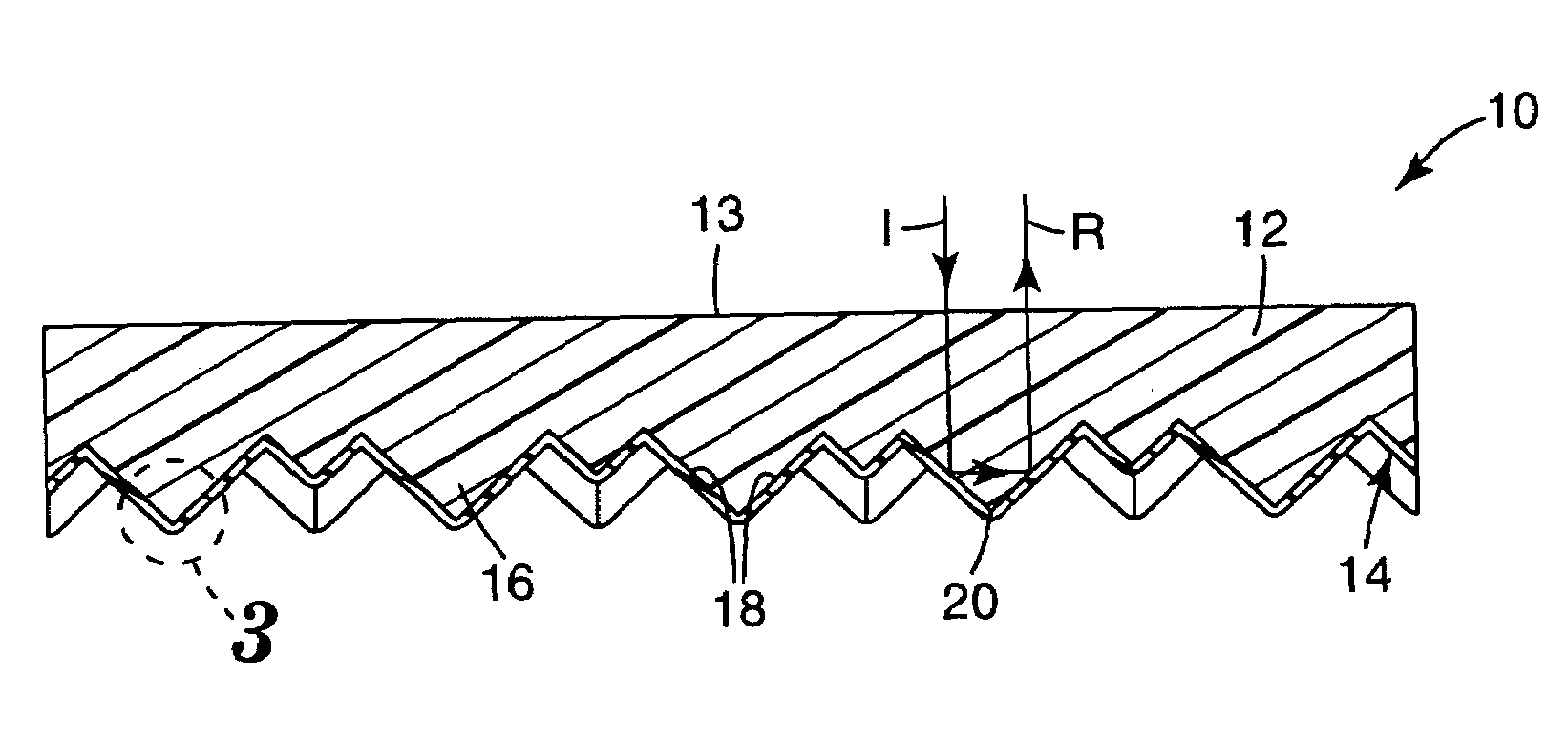
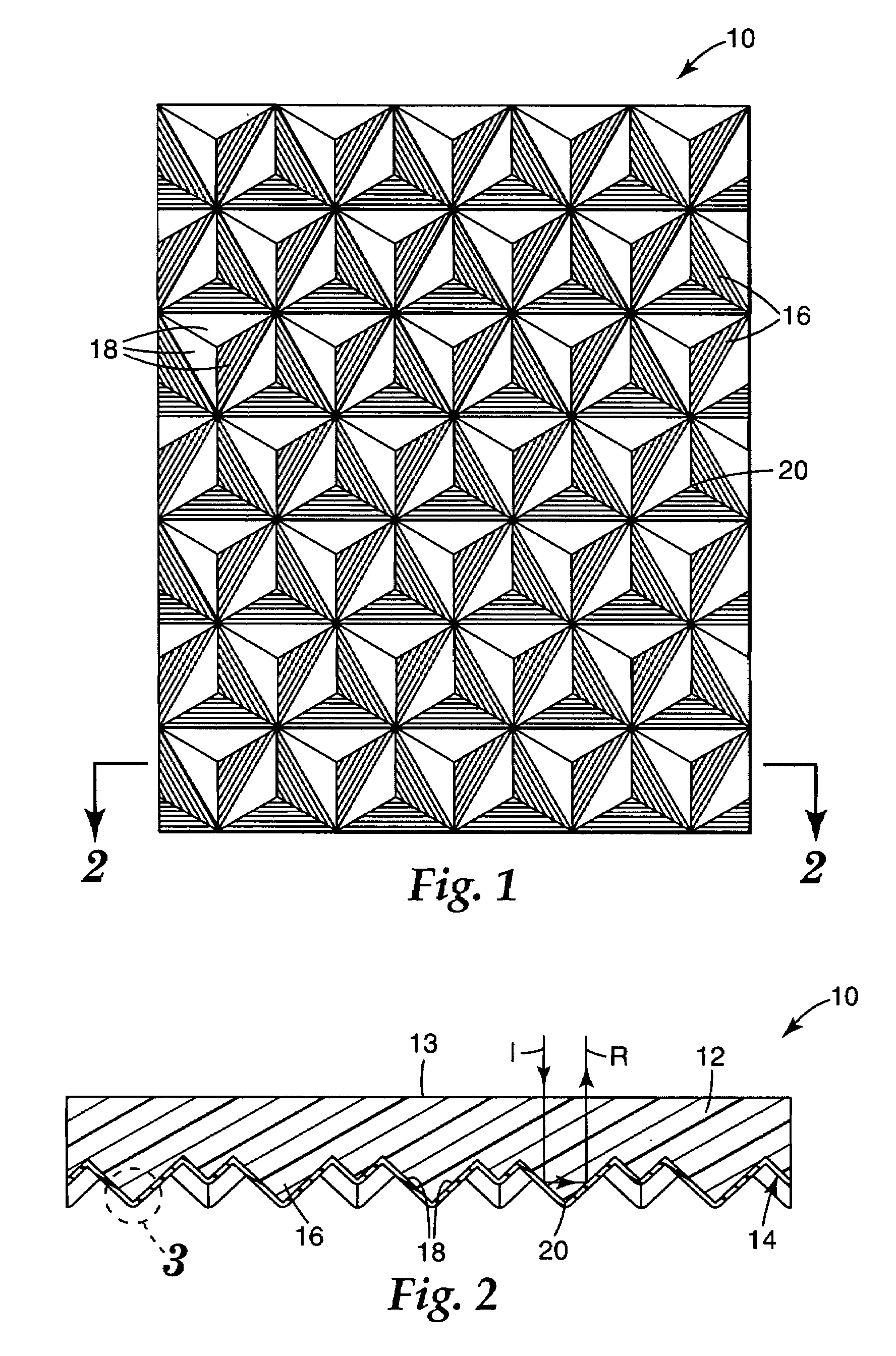
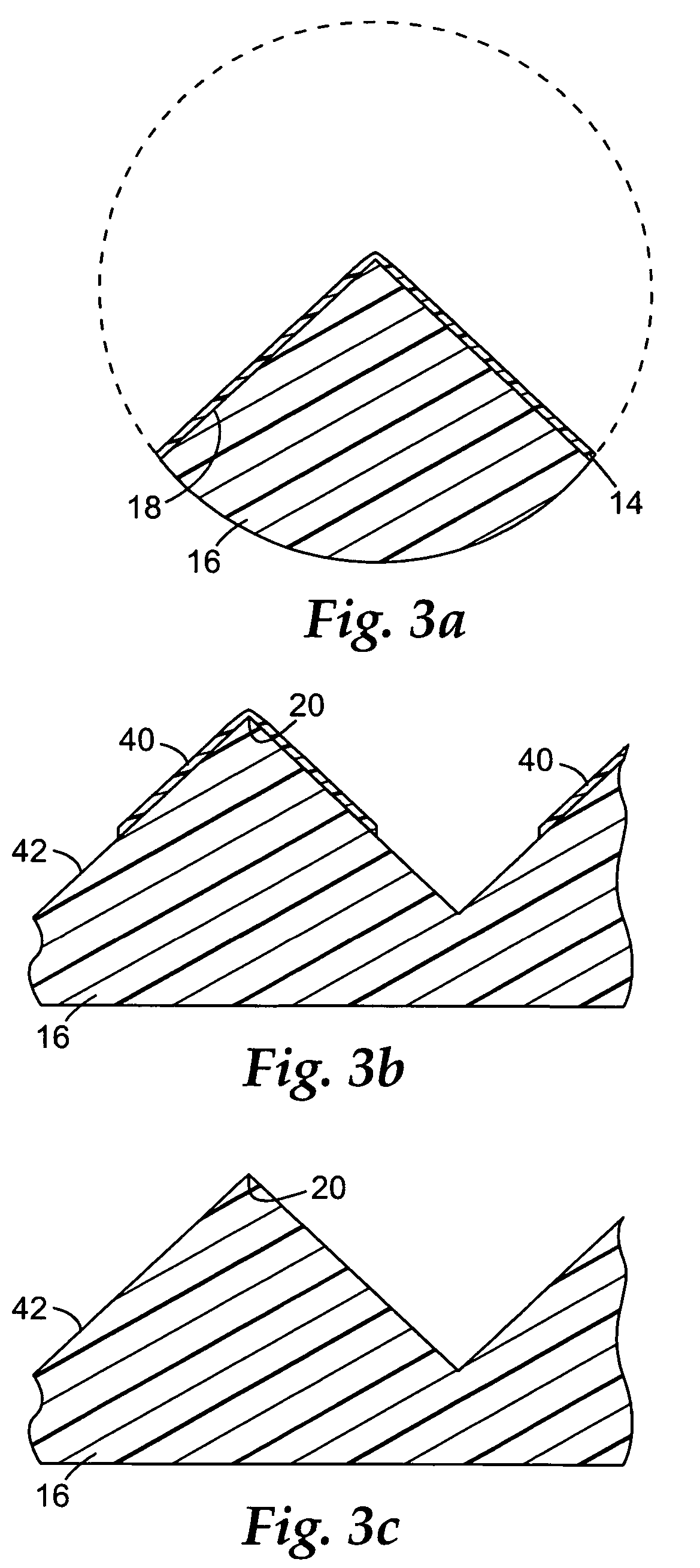
The patent text describes a new type of prismatic retroreflective article that eliminates the need for a rear cover film and reduces the stiffness and weight of the article. The article includes a transparent body portion and a layer of internally reflecting cube-corner optical elements that have an open air-exposed rear surface. The rear surface is made more hydrophobic, oleophobic, or both, which helps maintain retroreflectivity even when the cube-corner elements become wet or soiled. The article can be used in various applications such as reflective footwear or apparel, roll-up signs, and underwater applications. The patent also describes a method for making the prismatic retroreflective article by treating or coating the cube-corner optical elements to make them more hydrophobic, oleophobic, or both.

Problems solved by technology

However, rear cover film 158 significantly increases the weight and cost of article 150, and the seal legs 162 reduce the number of cube-corner elements available for retroreflection.
However, the resulting retroreflective article can lose most or all of its retroreflectivity when the exposed cube-corner elements become wet or soiled.
This can present particular problems in outdoor, athletic apparel, fire safety and underwater applications.

Method used


Image

  • Prismatic retroreflective article and method
  • Prismatic retroreflective article and method
  • Prismatic retroreflective article and method

Examples


example 1

[0040]Samples of unsealed cube-corner retroreflective sheeting (having a body layer made from a 0.05 mm thick polyethylene terephthalate glossy top film heat laminated to a 0.11 mm thick polyvinyl chloride film and against which were formed 0.09 mm high UV-cured acrylic cube-corner elements) were plasma-treated in an apparatus like that shown in FIG. 5 using the various treatment conditions shown below in Table I:

[0041]

TABLE IFlowPlasmaLineRunRate,Pressure,Power,Speed,No.Treatment Materialscm3mTorrWm / min.1-1Perfluoropropane60030025001.51-2Perfluoropropane600300250061-3Tetramethylsilane44450–1002001.51-4Tetramethylsilane44450–1002006

[0042]The treated samples were placed flat on a horizontal surface with the cube-corner optical elements facing up. A series of isopropyl alcohol / water mixtures containing 0 to 100 percent isopropyl alcohol and 100 to 0 percent water in 10 percent increments was applied to the treated samples and to a similarly positioned untreated sample. None of the alc...

example 2

[0045]Samples of unsealed cube-corner retroreflective sheeting (having a body layer made from a 0.19 mm thick plasticized polyvinyl chloride film against which were formed 0.09 mm high UV-cured cube-corner elements similar to those employed in Example 2, Composition C-2 of U.S. Pat. No. 5,691,846, but using hexanediol diacrylate in place of tetrahydrofurfuryl acrylate) were plasma-treated in an apparatus like that shown in FIG. 5 using the various treatment conditions shown below in Table II.

[0046]

TABLE IIFlowPlasmaLineRate,Pressure,Power,Speed,Run No.Treatment Materialscm3mTorrWm / min.2-1Perfluoropropane600500225032-2 (1st pass)Oxygen1500150125012.22-2 (2nd pass)Perfluoropropane600150250012.22-3Tetramethylsilane / Oxygen444 / 2507540006.12-4 (1st pass)Oxygen1500150400012.22-4 (2nd pass)Tetramethylsilane / Oxygen444 / 2507540006.1

[0047]The cube side of the Run 2-1 and 2-2 samples was exposed to water, mineral oil, kerosene, mineral spirits and isopropanol. None of the applied liquids wet out...


PUM


Abstract

A prismatic retroreflective article has a transparent body portion and a layer of internally reflecting cube-corner optical elements having an open air-exposed rear surface at least a portion of which is more hydrophobic, more oleophobic, or both more hydrophobic and more oleophobic than the underlying cube-corner optical element. The article may be made by providing a transparent body portion bearing a layer of internally reflecting open air-exposed cube-corner optical elements; treating or coating at least a portion of the cube-corner elements to make the treated or coated portion more hydrophobic, more oleophobic, or both more hydrophobic and more oleophobic than the underlying cube-corner optical elements; and leaving such treated or coated portion exposed to the open air.

Description

FIELD OF THE INVENTION[0001]This disclosure relates to prismatic retroreflective articles for use in applications including footwear, apparel, signage and pavement markings.BACKGROUND[0002]Prismatic retroreflective articles typically employ a multitude of cube-corner optical elements to retroreflect incident light. The cube-corner elements project from the back surface of a rigid or flexible transparent body portion. Incident light enters the article at a front surface, passes through the body portion, is internally reflected by the cube-corner element facets, returns through the body portion and subsequently exits the front surface and returns towards the light source. Reflection at the cube-corner facets can occur by total internal reflection when the cube-corner elements are encased in a lower refractive index media (e.g., air), or by specular reflection when the cube-corner elements are coated with a suitably reflective structure such as a vapor deposited aluminum coating or a r...

Claims


Application Information

Patent Timeline
Patent Type & Authority Patents(United States)
IPC IPC(8): G02B5/122E01F9/615
CPCG02B5/124G02B5/122
Inventor BACON, JR., CHESTER A.KIRK, SETH M.DAVID, MOSES M.CURRENS, MICHAEL D.OWUSU, OSEI A.
Owner 3M INNOVATIVE PROPERTIES CO
Learn More