Francis turbine

a turbine and blade technology, applied in vessel construction, renewable energy generation, greenhouse gas reduction, etc., can solve the problems of reducing the efficiency of hydraulic machines, promoting wear and tear, and reducing the mass of machines, etc., to achieve the effect of too high cost price and too large mass

Active Publication Date: 2007-03-27
GE RENEWABLE TECH
View PDF13 Cites 16 Cited by
  • Summary
  • Abstract
  • Description
  • Claims
  • Application Information

AI Technical Summary

Benefits of technology

[0015]Each blade is formed by a skin constituting its lateral faces and defining a hollow internal volume of the blade. Such a structure makes it possible to envisage the creation of relatively thick blades without their mass being too great and without the cost price of material being too high. In that case, the skin may be metallic or made of composite material. It may also be provided that the skin be formed by assembling two plates respectively constituting the pressure side and the suction side surface of the blade. According to an advantageous aspect, the internal volume of the blade may be lined with a filling material.

Problems solved by technology

However, particularly in the case of rehabilitation, the conditions of use of the turbine may be modified, particularly by reduction of the speed of rotation and / or increase of the pressure head, in which case the orientation of the leading edge of the blades is no longer compatible with the angle of incidence of the jet of water.
In that case, eddies and / or phenomena of cavitation are created in the proximity of the pressure side and suction side surfaces of the blades, this reducing the efficiency of the hydraulic machine and promoting the phenomena of wear and tear.

Method used


Image

  • Francis turbine
  • Francis turbine
  • Francis turbine

Examples


Embodiment Construction

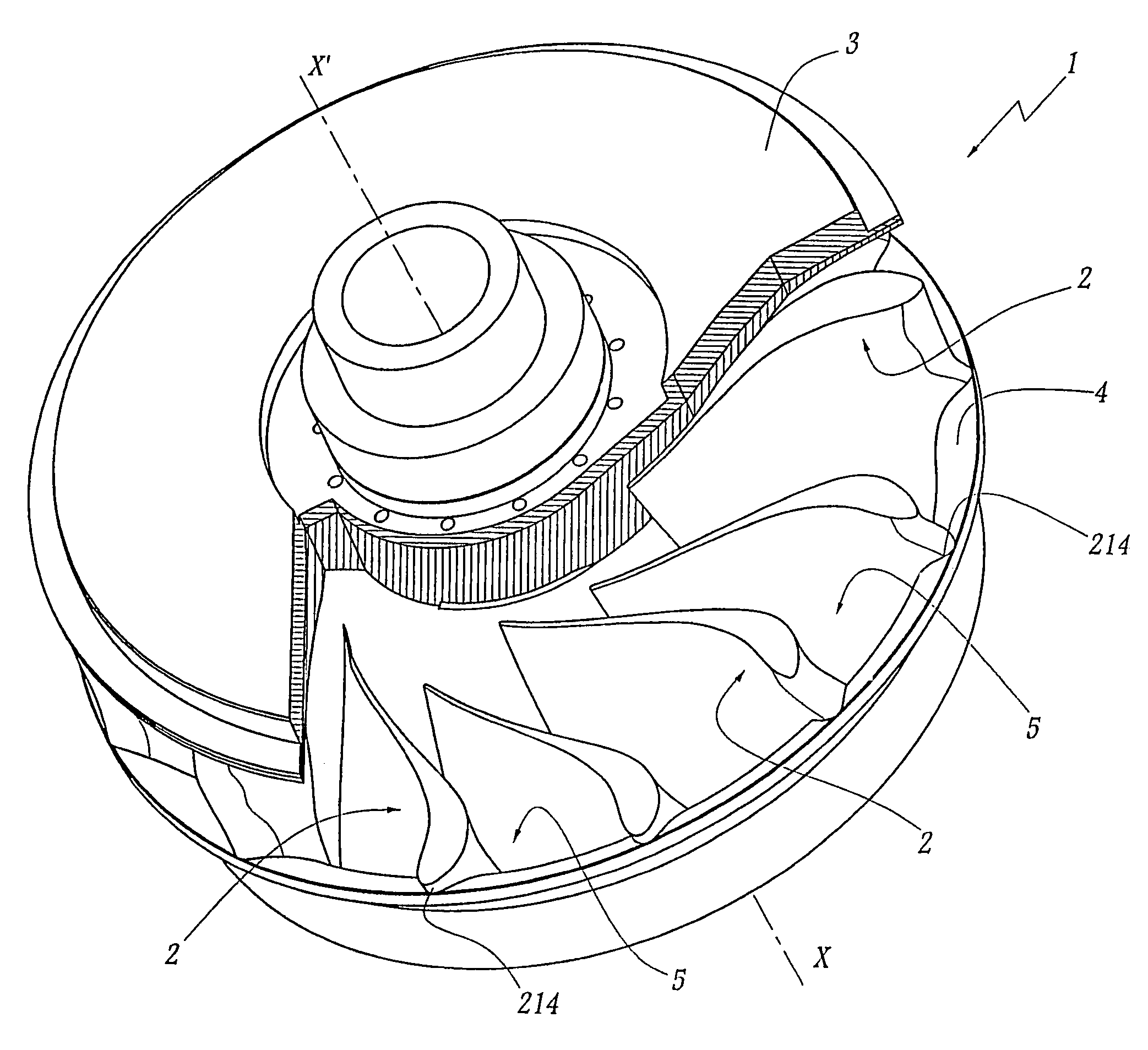
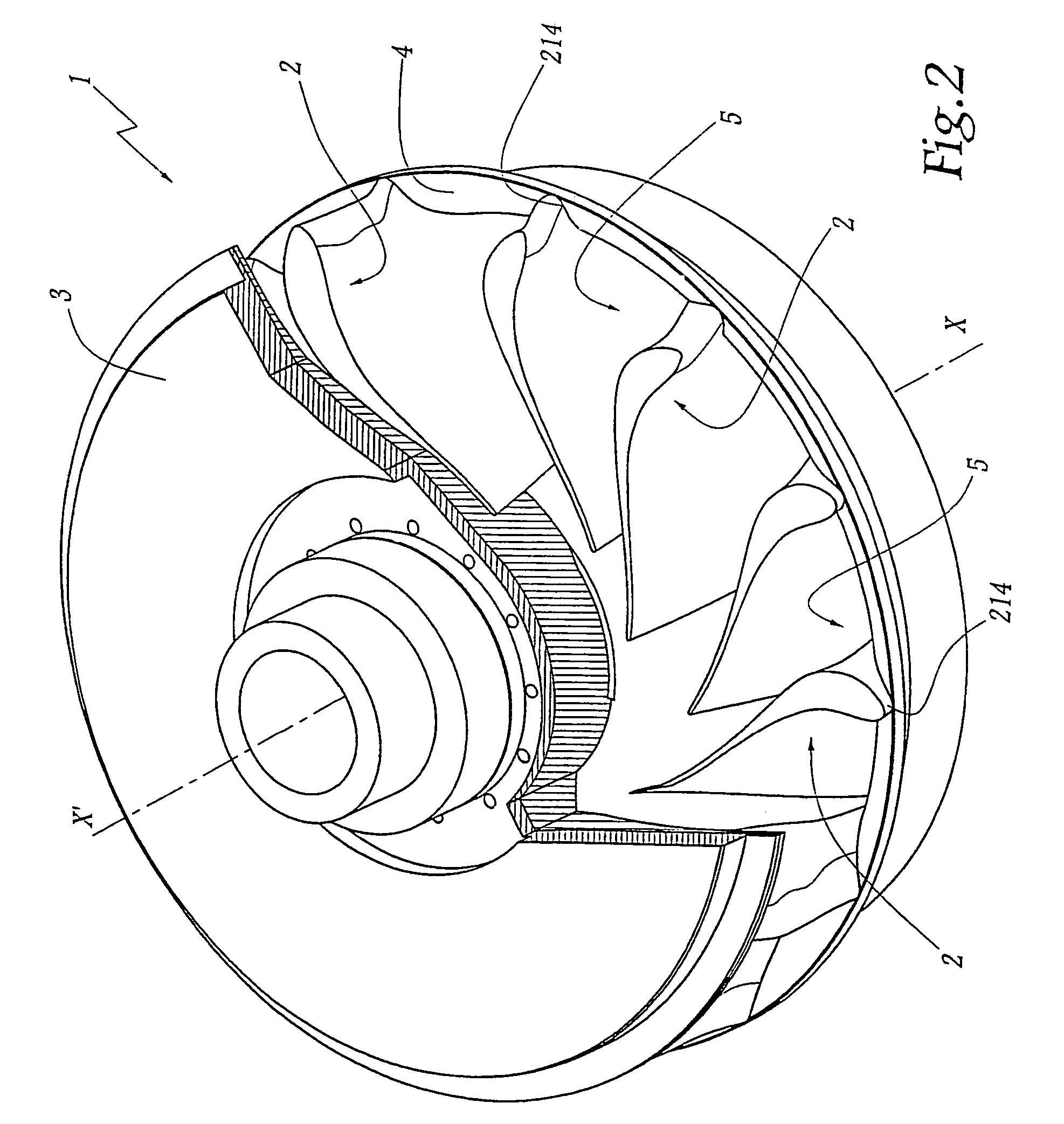
[0022]The runner 1 shown in FIGS. 2 to 4 comprises identical blades 2 distributed about a central axis X–X′ of rotation of the runner 1. A crown 3 is provided in the upper part of the runner 1, while a band 4 borders the lower, radial and external part of the blades 2. A flow channel 5 is thus defined between each pair of two adjacent blades 2, this channel being bordered by the crown 3 and the band 4.

[0023]21 denotes the leading edge of a blade 2.22 denotes its trailing edge. The average fibre 23 of the blade 2 is defined as being, in each transverse plane of this blade, a curve located at equal distance from the pressure side surface 24 and from the suction side surface 25 of the blade 2.

[0024]L denotes the average length of this fibre 23, this average being taken as equal to the half-sum of the length of the average fibre of a blade 2 at the level is of the crown 3 and at the level of the band 4.

[0025]e denotes the maximum thickness of the blade 2.

[0026]The geometry of the blade ...


PUM


Abstract

A Francis runner and a hydraulic turbine equipped with such a runner, wherein the runner includes a ceiling, a belt, and blades which extend between the ceiling and the belt and which define liquid flow channels therebetween. A ratio (e/L) of a maximum thickness Ce) of each blade to an average developed length (L) of an average fibre of each blade is between 0.1 and 0.2. At a leading edge of each blade, the average fibre is oriented, over essentially an entire height of the leading edge, along a straight line (Δ23), which forms an angle (α) greater than 90° relative to a line (U) defining a direction of rotation of the leading edge of the runner.

Description

BACKGROUND OF THE INVENTION[0001]1. Field of the Invention[0002]The invention relates to a Francis runner and to a turbine equipped with such a runner.[0003]2. Description of the Related Art[0004]Francis runners may equip different sorts of hydraulic machines, such as turbines, pumps, or pump turbines. They comprise blades distributed about a central rotating shaft and which define therebetween channels for flow of water. In the case of turbines, the geometry of the blades of these runners is defined so that the flow of the water induces a torque on the runner. The power that a turbine equipped with such a runner can deliver depends on its geometry, particularly on its diameter, in connection with its speed of rotation.[0005]In certain configurations of a Francis hydraulic machine, the diameter of the runner is imposed, particularly in the case of rehabilitation of an installation where the diameter cannot be modified without considerable civil engineering works.[0006]In the case of...

Claims


Application Information

Patent Timeline
Patent Type & Authority Patents(United States)
IPC IPC(8): F01D5/12F03B13/10F03B3/12
CPCF03B3/125Y02E10/223F05B2240/301Y02E10/20
Inventor BAZIN, DANIELECOUSTON, MICHEL HENRI
Owner GE RENEWABLE TECH
Why Eureka
Try Eureka