Heat insulating paper cups

Inactive Publication Date: 2007-03-27
DIXIE CONSUMER PROD
63 Cites 29 Cited by

AI-Extracted Technical Summary

Problems solved by technology

Such cups have outstanding heat-insulating properties, but require a lot of energy to make, and are costly to dispose of in an environmentally acceptable way.
Unfortunately, most attempts to produce paper-based heat-insulating cups have proved costly due to the complexity of their manufacturing processes.
These cups, however, have proved to be aesthetically unappealing and structurally deficient.
Also such cups are not easily nested making storage difficult.
The dual structure adds to manufacturing co...

Benefits of technology

[0014]An improved seal is a relative characteristic, and for purposes of this invention it is intended to be relative to seals in cups made in the same way except using an inside surface of the body member coated with 100% high density polyethylene. When mass producing cups according to the present invention an improved seal can be obtained using conventional cup-forming machines. When making 12 ounce cups using the HORAUF MODEL BMP-200 (with temperature controls set at between about 350° to about 460° C. and a bottom expansion pressure set at about 3000 kilopascals for two revolutions per cup), for example, sealing can be obtained at higher than normal fabrication speeds such as more than about 165 cups per minute, preferably even about 200 cups/minute or more, which is at least comparable to that obtained with 100% high density cups made at slower, more conventional speeds such as about 165 cups per min...

Abstract

A heat insulating paper cup having an improved seal. The cup can include a body member having an inside surface and an outside surface, and a bottom panel member having a upper surface and a bottom surface. The body member is coated (or in some instances partially coated) on its outside surface with a foamed low density polyethylene, and on its inside surface with an unfoamed modified low density polyethylene. The bottom panel member is coated on its upper surface with a foamed or an unfoamed low density polyethylene or foamed or unfoamed modified low density polyethylene. The body member and bottom panel member are oriented and joined to form a heat seal at an interface between a portion of the unfoamed modified low density polyethylene coated on the inside surface of the body member and a portion of unfoamed low density polyethylene or unfoamed modified low density polyethylene coated on the upper surface of the bottom panel member.

Application Domain

Boxes/cartons making machineryDomestic cooling apparatus +21

Technology Topic

Image

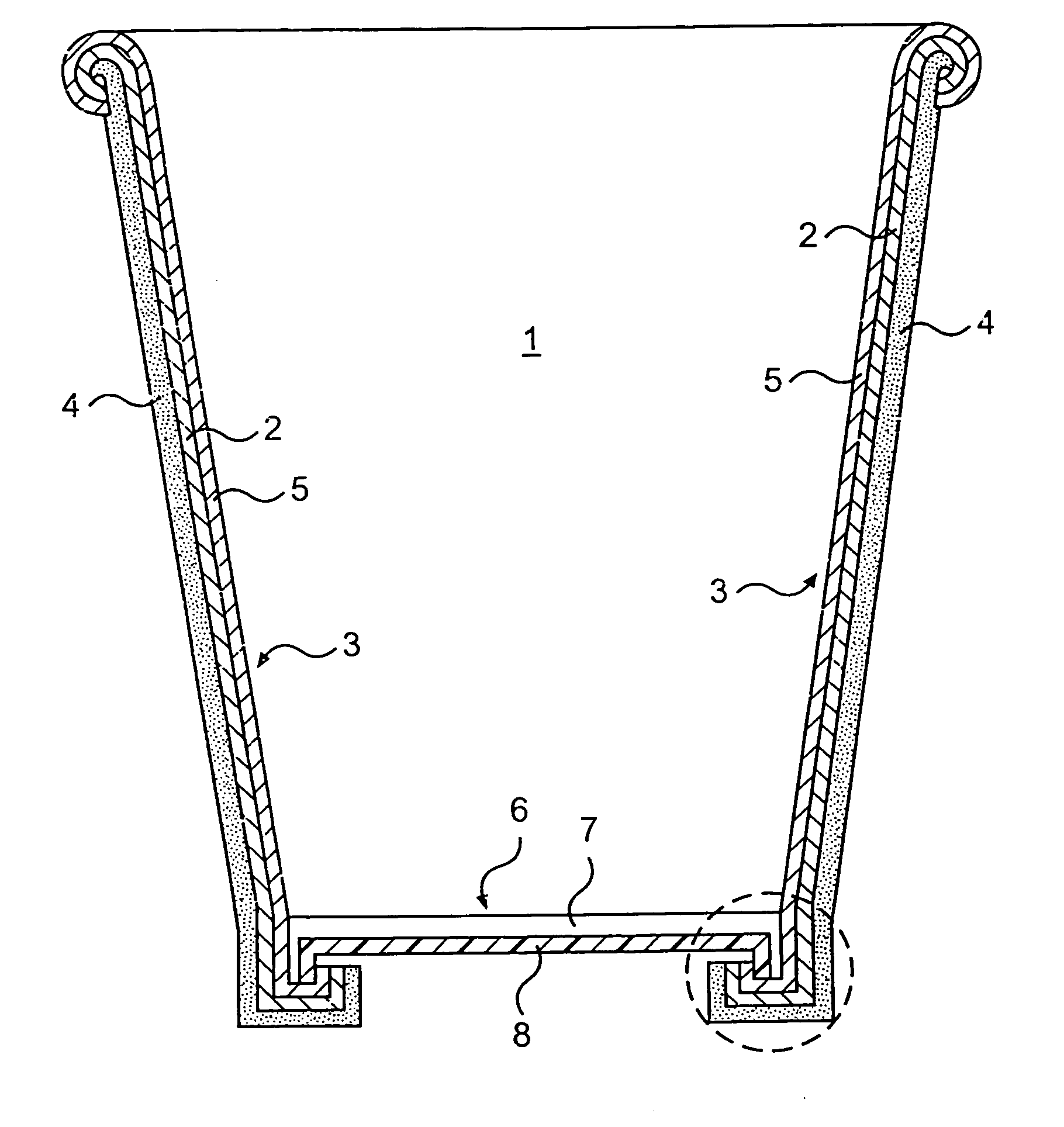
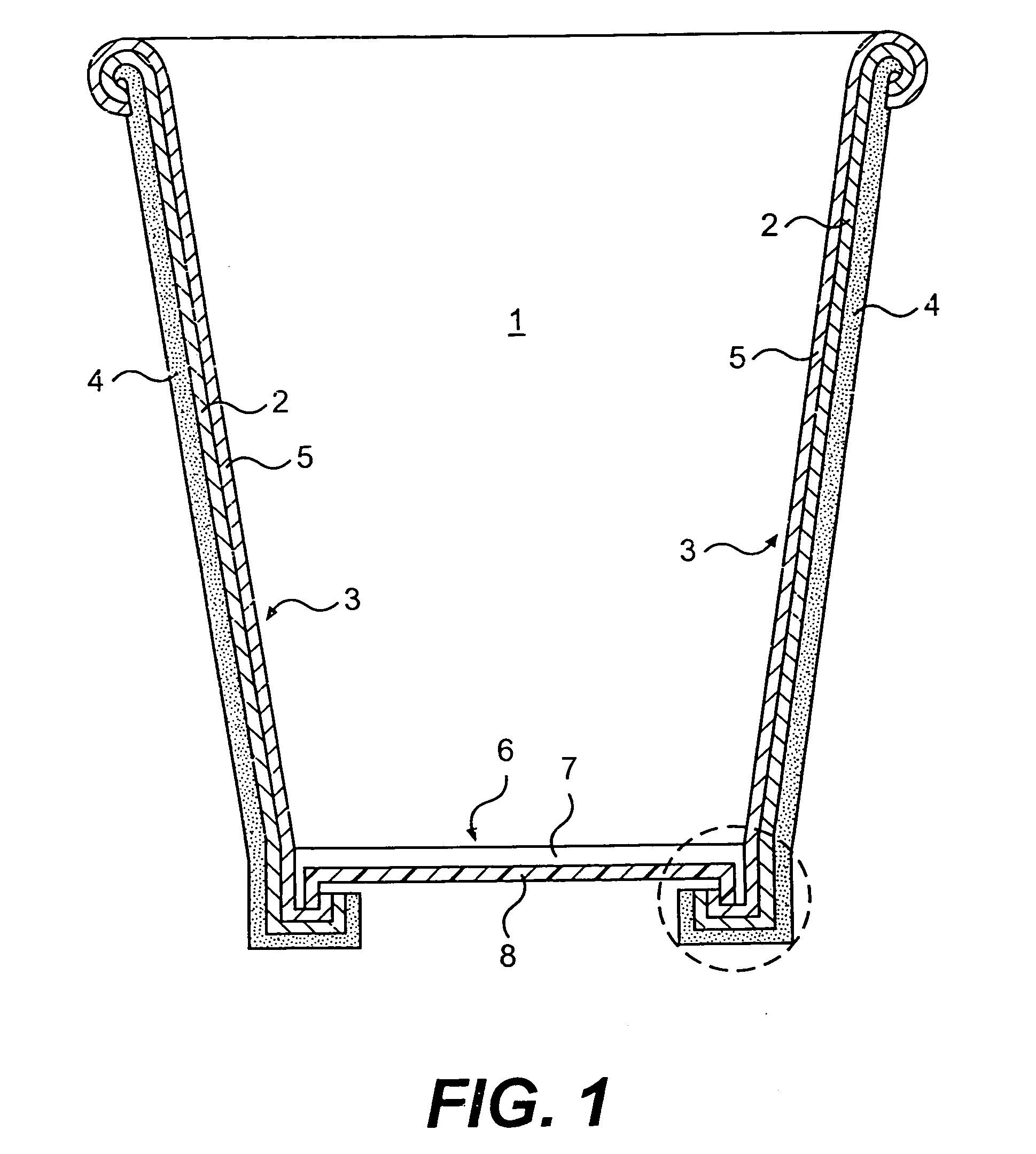
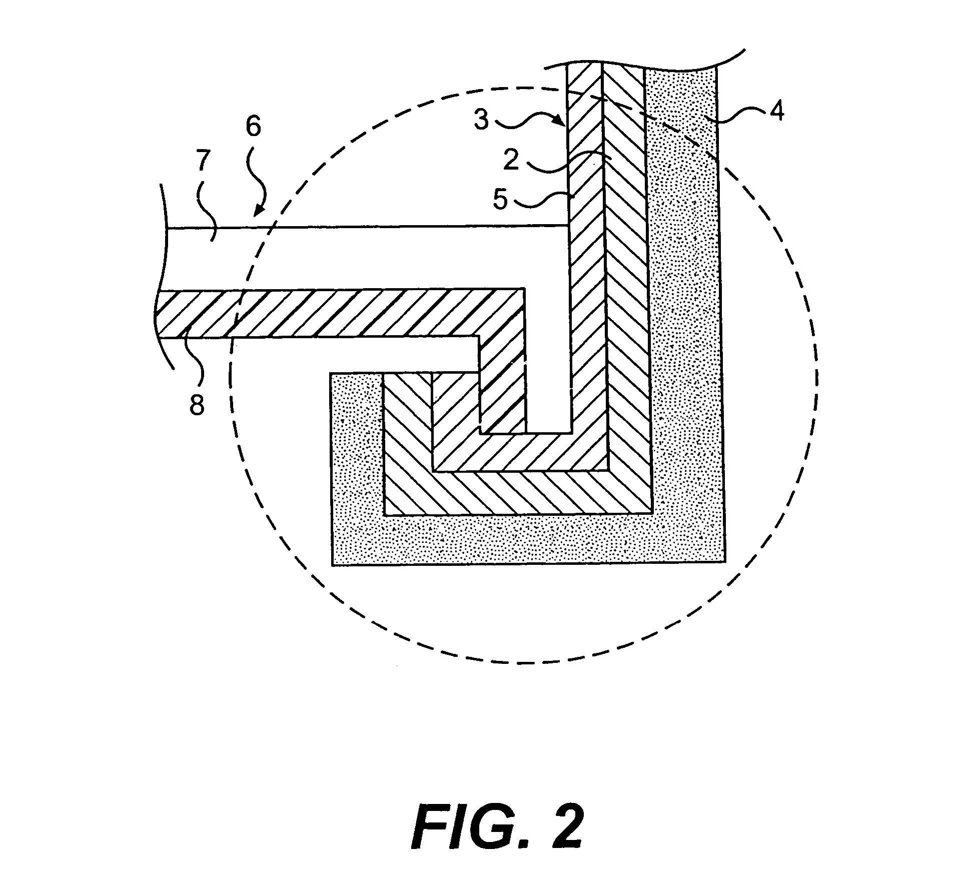
  • Heat insulating paper cups
  • Heat insulating paper cups
  • Heat insulating paper cups

Examples

  • Experimental program(2)

Example

EXAMPLE 1
[0038]Sidewalls for heat insulating paper cups were fabricated with their inside surfaces coated with Chevron PE 4517 low density polyethylene blended with varying amounts of Eastman M2004-P high density polyethylene. For purposes of comparison, one sample was prepared using an inside coating of 100% Eastman M2004-P high density polyethylene, and one sample was prepared using an inside coating of 100% Chevron PE 4517 low density polyethylene. The melting point for the polyethylene components present in each inside surface coating was determined using differential scanning calorimetry (DSC).
[0039]Each sidewall sample was heat treated for about 1.5 minutes using a conventional production oven at 270° F. (132° C.). The samples were then examined to determine whether foaming occurred on the inside surface of the sidewall.
[0040] MELTING SURFACE SAMPLE POINT (° C.) FOAMING? 100% HDPE 131 NO 60/40% LDPE/HDPE 107/125 NO 70/30% LDPE/HDPE 107/124 NO 80/20% LDPE/HDPE 107/125 NO 90/10% LDPE/HDPE 107/123 NO 100% LDPE 110 YES

Example

EXAMPLE 2
[0041]The heat sealabilities were evaluated for 1 inch wide polyethylene coated paper board samples prepared according to Example 1. For each test, the coated side of a sidewall sample was placed in contact with a control bottomstock coated with Chevron 4517 low density polyethylene, and a seal was effected using a Sentinel Heat Sealer Model No. 12ASL (serial no. 12-1120) available from Packaging Industries, Inc. of Hyannis, Mass. One inch sealing bars covered with Teflon tape were used to effect the seals at a temperature of 300° F. (149° C.) for the top and bottom bars; a jaw pressure of 40 psi; and a dwell time of 0.6 second.
[0042]The strengths of the heat sealed samples were then tested using an Model 4202 Instron Tensile Tester available from Instron Corp. of Canton, Mass. Each sealed sample was peeled apart at a 180° angle at a crosshead speed of 1 inch per minute. The peeled samples were then inspected to determine whether the joint failed to exceed the strength of the board (no fiber tear) or exceeded the strength of the board (fiber tear). A fiber tear was indicated by visible paperboard fibers on both peeled surfaces, and was indicative of an improved bond. This heat seal test is representative of effective substantially leak-free cup seals.
[0043] SAMPLE FIBER TEAR BOND? 100% HDPE NO 60/40% LDPE/HDPE YES 70/30% LDPE/HDPE YES 80/20% LDPE/HDPE YES 90/10% LDPE/HDPE YES 100% LDPE YES
[0044]Although the invention has been described above in terms of preferred embodiments, it is to be understood that variations and modifications may be resorted to as will be apparent to those skilled in the art. Such variations and modifications are to be considered within the purview and scope of the claims appended hereto. For example, the specification refers to improved seals which can be obtained according to the invention using materials effective to obtain such seals. Whether an improved seal exists or can be obtained can be determined by fabricating a twelve ounce cup using a HORAUF MODEL BMP-200 machine, with temperature controls set at between about 350° to about 460° C. and a bottom expansion pressure set at about 3000 kilopascals for two revolutions per cup. This does not mean that the invention is limited to only twelve ounce cups or to cups made by the recited machine using the recited fabrication conditions. Furthermore, the invention is intended to cover all paperboard containers having at least one foamed polyethylene surface (or a portion of the surface is foamed), whether or not they are “cups”. Of course the containers or cups may also contain more than one foamed surface as well. Other possible modifications could include the use of hybrid polyethylenes such as the so-called “medium density” polyethylenes (0.926 to 0.940 g/cm3 and Tpeak of about 115° C.) and “linear low density” polyethylenes (Tpeak of about 121 to 126° C.).

PUM

PropertyMeasurementUnit
Temperature115.55555555555556°C
Temperature132.22222222222223°C
Length2.5E-5 ~ 6.0E-5m
tensileMPa
Particle sizePa
strength10

Description & Claims & Application Information

We can also present the details of the Description, Claims and Application information to help users get a comprehensive understanding of the technical details of the patent, such as background art, summary of invention, brief description of drawings, description of embodiments, and other original content. On the other hand, users can also determine the specific scope of protection of the technology through the list of claims; as well as understand the changes in the life cycle of the technology with the presentation of the patent timeline. Login to view more.

Similar technology patents

Open-bottom automatic discharging tank device

InactiveCN101746580AImprove sealingRealize automatic unloadingFlexible coversWrappersCharge and dischargeCushion
Owner:TAIYUAN UNIVERSITY OF SCIENCE AND TECHNOLOGY

Classification and recommendation of technical efficacy words

  • Improve sealing
  • High density

Embolic filter frame having looped support strut elements

InactiveUS20040093012A1Longitudinal compliance be enhanceImprove sealingSurgeryDilatorsEngineeringLower degree
Owner:WL GORE & ASSOC INC

Variable frequency automated capacitive radio frequency (RF) dielectric heating system

InactiveUS20020047009A1Improve sealingLowering gap impedanceMeat/fish preservation by heatingDielectric heating circuitsRadio frequencyHeating system
Owner:THE STATE OF OREGON ACTING BY & THROUGH THE OREGON STATE BOARD OF HIGHER EDUCATION ON BEHALF OF OREGON STATE UNIV +1

Active grill shutter vane design and vehicle system

InactiveUS20130223980A1Minimal pressure dropImprove sealingWind motor controlPump componentsAirflowAerodynamics
Owner:SHAPE CORP
Why Eureka
Try Eureka