Polymeric separator plates

a technology of polymer separators and separator plates, which is applied in the direction of paper/cardboard containers, sustainable manufacturing/processing, non-metal conductors, etc., can solve the problem of inefficiency in high-voltage fuel cell operation

Inactive Publication Date: 2007-03-27
GM GLOBAL TECH OPERATIONS LLC
View PDF13 Cites 14 Cited by
  • Summary
  • Abstract
  • Description
  • Claims
  • Application Information

AI Technical Summary

Problems solved by technology

Aqueous based coolants are a viable and desirable option from a thermal load standpoint; however, these same coolants are easily contaminated with ionic species that support undesirable electrolysis and corrosion reactions at the separator plate surface, creating inefficiency in high voltage fuel cell operation.

Method used


Image

  • Polymeric separator plates
  • Polymeric separator plates
  • Polymeric separator plates

Examples


Embodiment Construction

[0013]The following description of the preferred embodiment(s) is merely exemplary in nature and is in no way intended to limit the invention, its application, or uses.

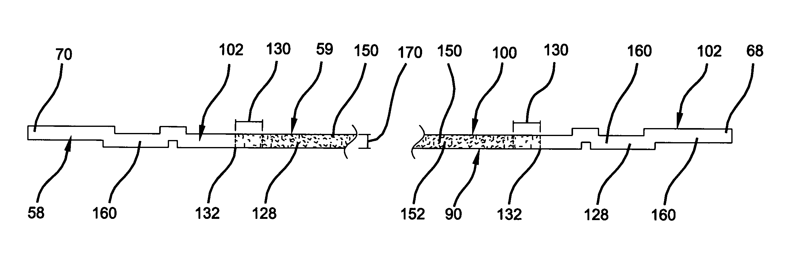
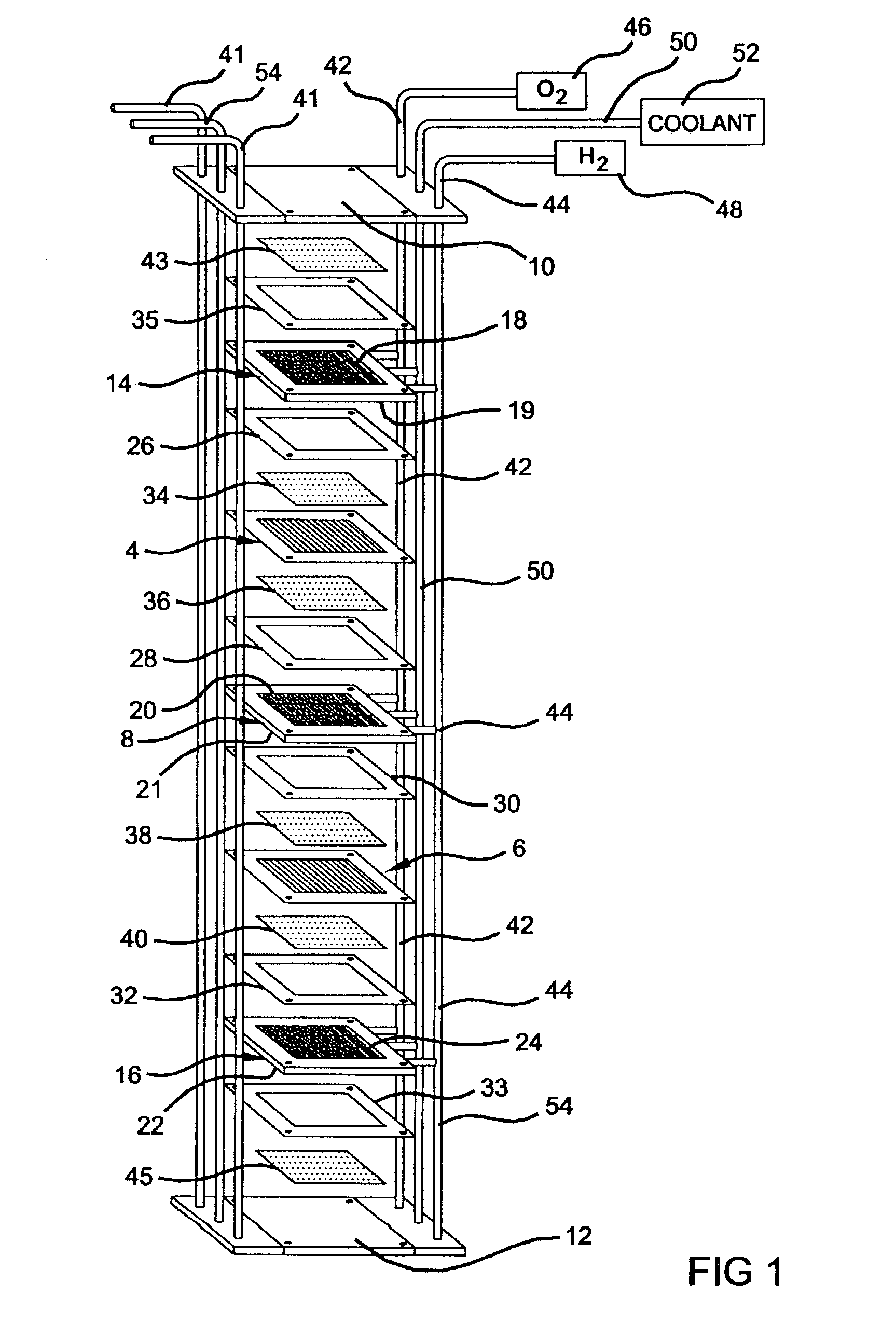
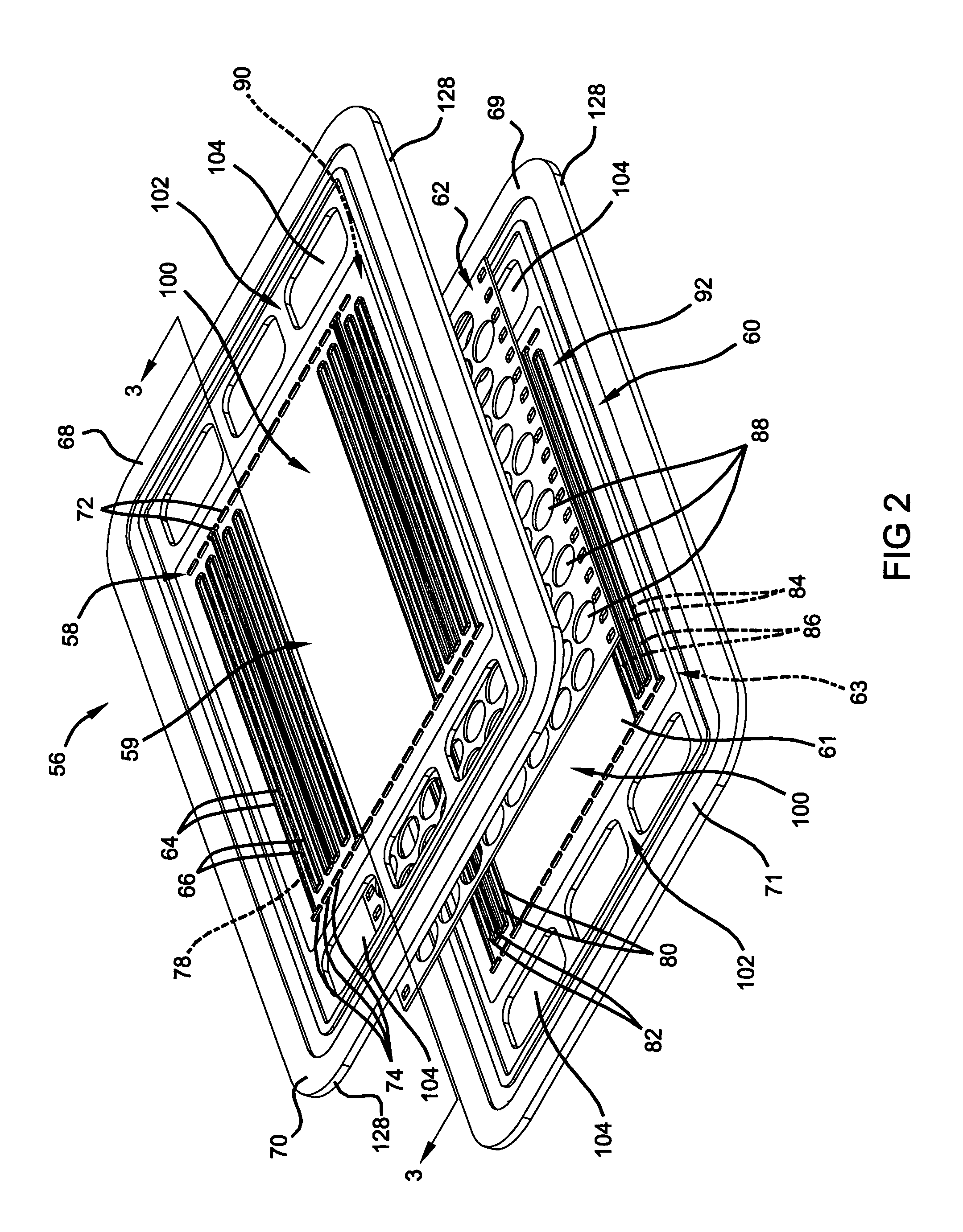
[0014]The present invention contemplates a separator plate in an electrochemical fuel cell stack that has a body with an electrically conductive first section having fluid flow fields with a plurality of flow channels formed therein and a second section adjacent to the first section that has a header area defining a manifold for supplying fluids to each individual fuel cell, and more particularly, to the respective flow fields of each fuel cell. The second section is non-conductive to prevent possible electrical interaction with any aqueous fluids (of finite ionic conductivity) present in the fuel cell, which may result in inefficient fuel cell operations. Further, the present invention contemplates methods to form such a separator plate. First, to better understand the present invention, a description of an exemplary...


PUM

PropertyMeasurementUnit
temperaturesaaaaaaaaaa
temperatureaaaaaaaaaa
electrically conductiveaaaaaaaaaa

Abstract

A separator plate in an electrochemical cell and method for making the same includes a body with an electrically conductive first section having fluid flow fields with a plurality of flow channels formed therein. A second section is provided adjacent to the first section that has a header area defining a manifold that supplies fluids to the flow fields of each fuel cell. The second section is non-conductive to prevent possible electrical interaction with any aqueous fluids of finite ionic conductivity present in the fuel cell, which may result in inefficient fuel cell operations.

Description

FIELD OF THE INVENTION[0001]The present invention relates to PEM fuel cells and, more particularly, to polymeric separator plates and methods for making the same.BACKGROUND OF THE INVENTION[0002]Fuel cells have been proposed as a power source for electric vehicles and other applications. One known fuel cell is the PEM (i.e., Proton Exchange Membrane) fuel cell that includes a so-called “membrane-electrode-assembly” comprising a thin, solid polymer membrane-electrolyte having an anode on one face of the membrane-electrolyte and a cathode on the opposite face of the membrane-electrolyte. The anode and cathode typically comprise finely divided carbon particles, having very finely divided catalytic particles supported on the internal and external surfaces of the carbon particles, and proton conductive material intermingled with the catalytic and carbon particles.[0003]The membrane-electrode-assembly is sandwiched between a pair of electrically conductive contact elements which serve as ...

Claims


Application Information

Patent Timeline
Patent Type & Authority Patents(United States)
IPC IPC(8): H01M2/00B31B1/60B32B15/08B32B17/06B32B19/00B32B27/06B32B27/28H01B1/06H01MH01M2/14H01M8/02
CPCH01M8/0204H01M8/0221H01M8/0226Y10T156/10Y02E60/50Y02P70/50
Inventor LISI, DANIEL JBLUNK, RICHARD HOWENS, JOHN NMIKHAIL, YOUSSEF MABD ELHAMID, MAHMOUD H
Owner GM GLOBAL TECH OPERATIONS LLC
Why Eureka
Try Eureka