Flat cable, flat cable sheet, and flat cable sheet producing method

a flat cable and production method technology, applied in the direction of flat/ribbon cables, insulated conductors, cables, etc., can solve the problems of difficult to reduce the production cost of coaxial cables, and the flat cables disclosed in japanese patent publications cannot be suitably used for transmitting radio frequency signals. , to achieve the effect of flexible wired

Inactive Publication Date: 2007-03-27
SONY CORP
View PDF26 Cites 25 Cited by
  • Summary
  • Abstract
  • Description
  • Claims
  • Application Information

AI Technical Summary

Benefits of technology

[0008]Therefore, an object of the present invention is to provide a flat cable that can be flexibly wired. Another object of the present invention is to adjust the size of the cross-section of a signal line for a designated characteristic impedance and to provide a flat cable having a sufficiently wider ground layer than the signal line.
[0009]In addition, a further object of the present invention is to provide a flat cable that can be produced at low cost.
[0015]According to the present invention, the size of the cross-section of a signal line, the thickness of the dielectric layer and so forth are selected to obtain a predetermined characteristic impedance for the cable. In addition, a flat cable composed of a ground layer that is sufficiently wider than a signal line and a dielectric sheet that has plasticity can be produced at low cost. When such a flat cable is used for an electronic apparatus, it can be miniaturized.

Problems solved by technology

In addition, since these layers should be cylindrically formed and deposited, a complicated production process is required.
It is therefore difficult to decrease the production cost of the coaxial cable 120.
However, the flat cables disclosed in these Japanese patent publications cannot be suitably used for transmitting radio frequency signals.
In this method, however, since the transmission lines cannot be freely bent, the method cannot be used for cables.

Method used


Image

  • Flat cable, flat cable sheet, and flat cable sheet producing method
  • Flat cable, flat cable sheet, and flat cable sheet producing method
  • Flat cable, flat cable sheet, and flat cable sheet producing method

Examples


first embodiment

(First Embodiment)

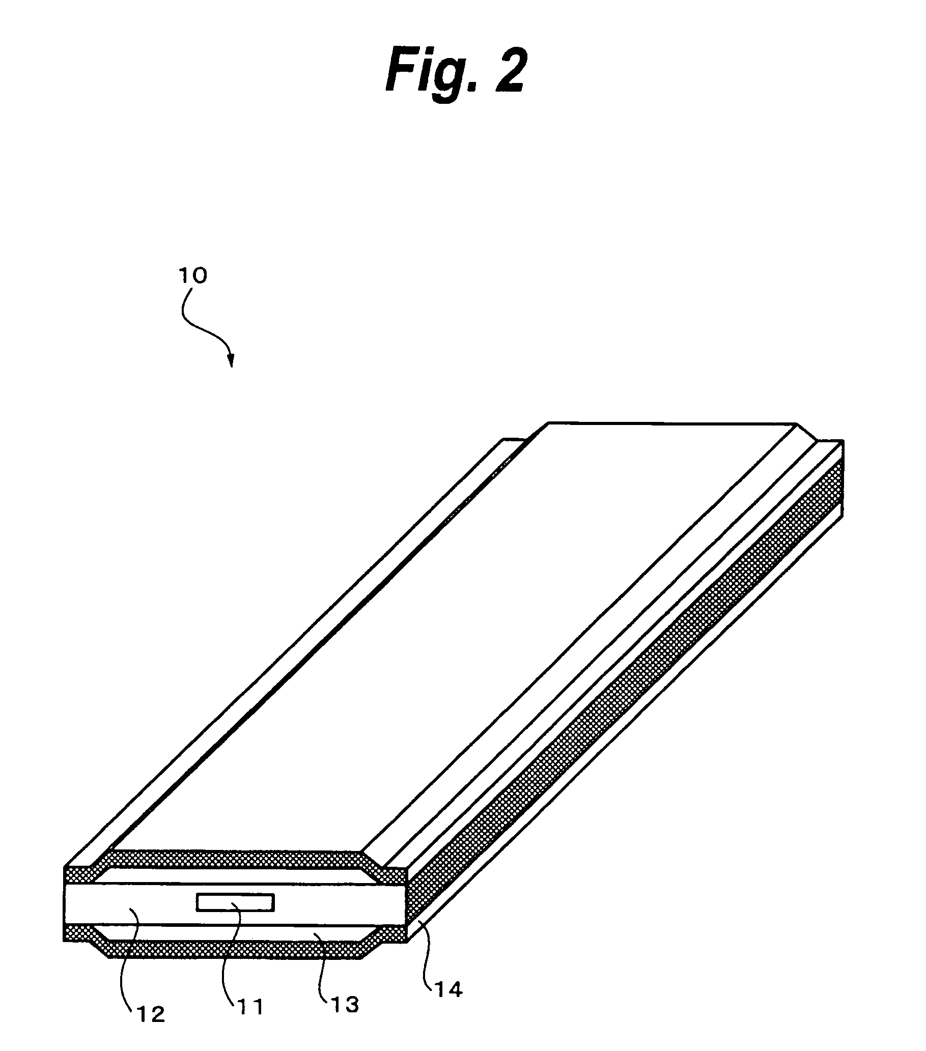
[0038]FIG. 2 shows the structure of a flat cable according to a first embodiment of the present invention. In FIG. 2, a cable 10 is a radio frequency cable that has a strip line structure. Since this cable is flat, it can be more flattened than conventional coaxial cables. In addition, when the dielectric substance is thinned and the ground layer is sufficiently wider than the signal line, the radiation of a signal from the side portion free of the ground layer can be suppressed. The characteristic impedance depends on the size of the cross-section of the signal line, the specific dielectric constant of the dielectric substance, and so forth. In this example, the flat cable is designated to have a characteristic impedance of 50Ω.

[0039]More particularly, the cable 10 is structured so that a signal line 11 is coated with a thin dielectric sheet 12 and ground layers 13 are formed on an upper surface and a lower surface of the dielectric sheet 12, the ground layers 13 ...

second embodiment

(Second Embodiment)

[0047]Next, with reference to FIG. 6, a flat cable according to a second embodiment of the present invention will be described. A cable 40 shown in FIG. 6 contains a signal line 41, a dielectric sheet 42, upper and lower ground layers 43, upper and lower shield layers 44, and upper and lower insulators 45. The signal line 41 is coated with the dielectric sheet 42. The upper and lower ground layers 43 are formed on the upper and lower surfaces of the dielectric sheet 42, respectively. Each of the ground layers 43 is sufficiently wider than the signal line 41. The upper and lower ground layers 43 are coated with the upper and lower insulators 45, respectively. The upper and lower shield layers 44 are formed on the upper and lower insulators 45, respectively. The upper and lower shield layers 44 are coated with the upper and lower insulators 45, respectively.

[0048]According to the second embodiment, the shield layers 44 and the insulators 45 are formed on the upper a...

third embodiment

(Third Embodiment)

[0050]Next, with reference to FIG. 7, a flat cable according to a third embodiment of the present invention will be described. A cable 50 shown in FIG. 7 is a cable having a coplanar structure in which a signal line 51 and two ground layers 53 are formed on the same plane (i.e., the surface of a dielectric sheet 52). Since the signal line 51 and the two ground layers 53 are formed on the same plane, namely on the dielectric sheet 52, the structure of this cable becomes simpler and it can be produced at lower cost than the foregoing cables.

[0051]The cable 50 is composed of a signal line 51, a dielectric sheet 52, two ground layers 53, and upper and lower insulators 54. As described above, the signal line 51 and the two ground layers 53 are formed almost in parallel in the longitudinal direction of the cable 50 so that the signal line 51 does not contact the two ground layers 53. In addition, the two ground layers 53 are formed on both sides of the signal line 51. In...


PUM

PropertyMeasurementUnit
radio frequencyaaaaaaaaaa
impedanceaaaaaaaaaa
thicknessaaaaaaaaaa

Abstract

A flat cable includes a signal line extending in a longitudinal direction, a thin dielectric sheet with which the signal line is coated and that has plasticity, a pair of spaced apart ground layers extending in the longitudinal direction and sandwiching the dielectric sheet in its thickness direction, and insulators that coat the pair of ground layers so that they are not exposed to the outside. The cross-sectional size of the signal line in a direction orthogonal to the longitudinal direction, the thickness and width of the dielectric sheet, and so forth are selected to obtain a predetermined characteristic impedance for the cable. Each of the pair of ground layers is sized so as to be substantially wider than the signal line.

Description

CROSS-REFERENCE TO RELATED APPLICATIONS[0001]The present application claims priority from Japanese Application No. 2004-065146 filed Mar. 9, 2004, the disclosure of which is hereby incorporated by reference herein.BACKGROUND OF THE INVENTION[0002]The present invention relates to a flat cable and a flat cable producing method, in particular, to a flat cable that can be produced at low cost and that can be densely mounted.[0003]In recent years, as various types of electronic devices that generate radio frequency signals have been developed, their use has become widespread. As a result, many electronic apparatuses are being used in offices and homes. These electronic apparatuses use coaxial cables as radio frequency signal cables.[0004]FIG. 1 shows the structure of a conventional coaxial cable. Disposed at the center of a coaxial cable 120 is a signal line 121. Disposed around the signal line 121 is a dielectric substance 122. Disposed around the dielectric substance 122 is a ground la...

Claims


Application Information

Patent Timeline
Patent Type & Authority Patents(United States)
IPC IPC(8): H01B7/00H01B7/08H01B11/00H01B13/00
CPCH01B7/0861H01Q9/285H01P3/085H01P3/003E04H6/42
Inventor TANAKA, NAOKIWASHIRO, TAKANORI
Owner SONY CORP
Why Eureka
Try Eureka