Ceramic lining plate of power module

A ceramic liner and power module technology, applied in the field of power module ceramic liner structure, can solve the problems of large inductance, complex liner interconnection, stray circuit interconnection structure, etc., to reduce stray inductance and high process efficiency , the effect of flexible wiring

Active Publication Date: 2018-03-06
ZHUZHOU CRRC TIMES SEMICON CO LTD
View PDF4 Cites 3 Cited by
  • Summary
  • Abstract
  • Description
  • Claims
  • Application Information

AI Technical Summary

Problems solved by technology

[0005] In view of this, the object of the present invention is to provide a power module ceramic liner to solve the problem that the existing power module ceramic liner circuit interconnection structure has large stray inductance, chip welding needs to use welding tools, and the metal layer on the front side of the liner is strong. The combination layer of electricity and weak electricity, and the technical problems of interconnection between lining boards are relatively complicated

Method used


Image

  • Ceramic lining plate of power module
  • Ceramic lining plate of power module
  • Ceramic lining plate of power module

Examples


Embodiment 1

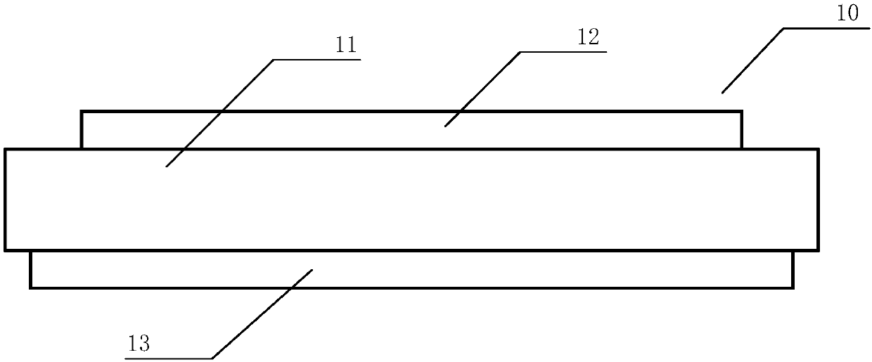
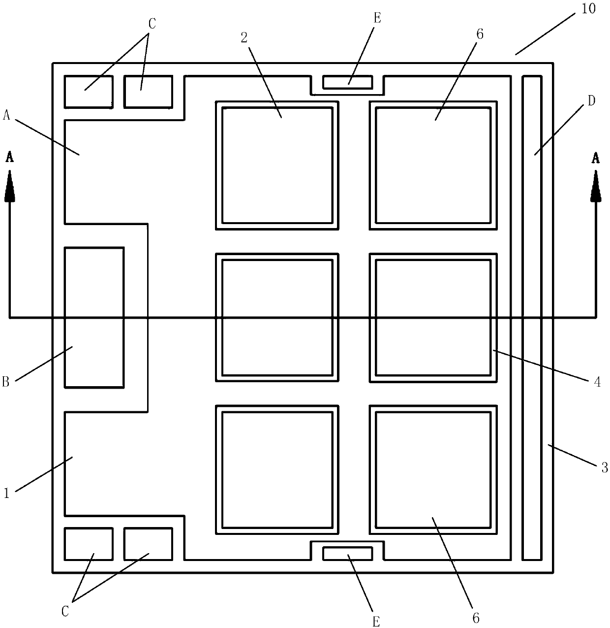
[0039] as attached image 3 As shown, a specific embodiment of a power module ceramic liner, the liner 10 adopts a multi-layer stacked structure with three layers of metal layers and two layers of ceramic layers arranged at intervals, and specifically includes: the first layer arranged in sequence from top to bottom Metal layer 1, second metal layer 2 and third metal layer 3. A first ceramic layer 4 is arranged between the first metal layer 1 and the second metal layer 2 , and a second ceramic layer 5 is arranged between the second metal layer 2 and the third metal layer 3 . Among them, the metal layer is made of copper, aluminum, gold, molybdenum and other materials, and the ceramic layer is made of AlN, Al 2 o 3 、Si 3 N 4 and other materials. as attached figure 2 As shown, the first metal layer 1 is arranged as an emitter region A (the emitter region A is also welded with emitter busbars) and a control signal terminal region C which are isolated from each other. The ...

Embodiment 2

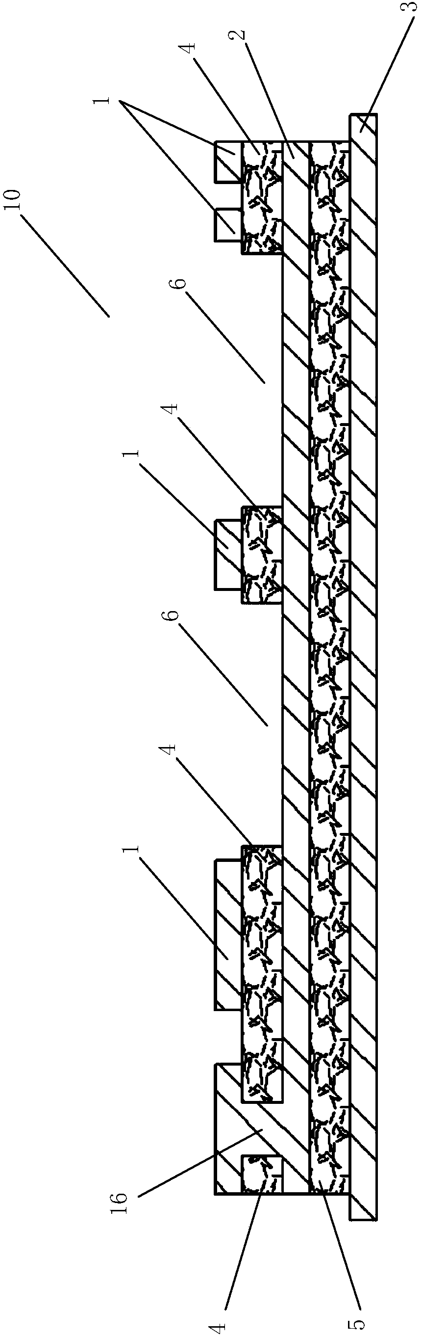
[0046] as attached Figure 6 As shown, a specific embodiment of a power module ceramic liner, the liner 10 includes: a first metal layer 1 , a second metal layer 2 and a third metal layer 3 arranged in sequence from top to bottom. A first ceramic layer 4 is arranged between the first metal layer 1 and the second metal layer 2 , and a second ceramic layer 5 is arranged between the second metal layer 2 and the third metal layer 3 . The first metal layer 1 is set as the emitter area A and the control signal terminal area C which are isolated from each other, and the second metal layer 2 is set as the collector area B. Grooves 6 for mounting the first power chip 20 and the second power chip 30 are formed on the upper surface of the substrate 10 along the thickness direction, and the grooves 6 extend from the first metal layer 1 to the second metal layer 2 . The groove 6 can pass through the first ceramic layer 4 from the first metal layer 1, and extend to the upper surface of the...


PUM

PropertyMeasurementUnit
sizeaaaaaaaaaa

Abstract

The invention discloses a ceramic lining plate of a power module. The ceramic lining plate comprises a first metal layer, a second metal layer and a third metal layer which are sequentially arranged from top to bottom, wherein a first ceramic layer is arranged between the first metal layer and the second metal layer, a second ceramic layer is arranged between the second metal layer and the third metal layer, the first metal layer is configured to be an emitter region and a control signal terminal region which are isolated with each other, the second metal layer is configured to be a collectorregion, the second metal layer also can further extend to an upper surface of the first ceramic layer via a through hole, grooves are formed in an upper surface of the lining plate along a thickness direction and are respectively used for installing a first power chip and a second power chip, and the grooves extend to the first metal layer from the first metal layer. By the ceramic lining plate, the technical problems that a circuit interconnection structure of the ceramic lining plate of an existing power module is large in stray inductance, a welding tool is needed to be used during chip welding, a metal liner on a front surface of the lining plate is a combination layer of strong electricity and weak electricity and interconnection between the lining plates is relatively complicated canbe solved.

Description

technical field [0001] The invention relates to the field of manufacturing power semiconductor devices, in particular to a power module ceramic liner structure. Background technique [0002] The substrate 10 is a basic unit structure of a power semiconductor module (such as an IGBT module), and plays multiple functions such as electrical interconnection, electrical insulation, and heat dissipation channels. The vertical structure of the traditional IGBT module liner is as attached figure 1 As shown, the ceramic liner adopts a three-layer structure, that is, one ceramic layer (ceramic layer 12) and two metal layers (front metal layer 11 and back metal layer 13), and the metal layer is isolated by the ceramic layer. The role of the ceramic layer is to insulate, prevent high voltage breakdown, and also play a role in heat dissipation. The function of the front metal layer is to realize circuit interconnection. Usually, the second power chip and the first power chip are placed...

Claims


Application Information

Patent Timeline
Patent Type & Authority Applications(China)
IPC IPC(8): H01L23/495H01L25/18
CPCH01L25/18H01L23/49503H01L23/49534H01L23/49558H01L23/49562H01L2224/48137H01L2224/4846H01L2224/48139H01L2224/49111H01L2224/4903H01L2224/48227H01L2224/73265H01L2224/0603H01L2924/19107H01L2224/49175H01L2224/49113
Inventor 常桂钦窦泽春方杰彭勇殿童颜李继鲁肖红秀徐凝华曾雄万超群
Owner ZHUZHOU CRRC TIMES SEMICON CO LTD
Why Eureka
Try Eureka