Method and apparatus for control of predistortion linearizer based on power series

a linearizer and power series technology, applied in the field of linearization of power amplifiers, can solve the problems of increasing the distortion component, not easy to generate compensation signals, and no desired frequency characteristics can be imparted to compensation signals

Inactive Publication Date: 2007-03-27
NTT DOCOMO INC
View PDF10 Cites 19 Cited by
  • Summary
  • Abstract
  • Description
  • Claims
  • Application Information

AI Technical Summary

Benefits of technology

[0009]It is therefore an object of the present invention to provide a concrete method and apparatus for controlling the power series predistortion linearizer that implement the frequency characteristics of the compensation signal. Another object of the invention is to provide a method and apparatus for controlling a power series predistortion linearizer that permit compensation for high-order distortion components as required.

Problems solved by technology

However, operation of the power amplifier around the saturation power region causes an increase in the distortion component.
However, the nonlinear characteristic of the power amplifier in the around the saturation power is so complex that it is not easy to generate a compensation signal which provides the above-mentioned amplitude and phase deviations for each odd-order distortion component.
Such memory effects leads to convolution of the distortion component by a band pass filter with certain characteristics, thereby adding a frequency characteristic to the distortion component that occurs in the power amplifier.
However, no desired frequency characteristics can be imparted to the compensation signal, and for this reason it is impossible to achieve high distortion compensation.
However, patent documents 2 and 3 do not clearly disclose how to obtain the desired frequency characteristics for the compensation signal.
When a certain order compensation signal is added by the predistortion linearizer, the added compensation signal leads to generation of a new distortion component at the output of the power amplifier.
As a result, there is possibility that the compensation for distortions of the other orders does not become optimum.

Method used


Image

  • Method and apparatus for control of predistortion linearizer based on power series
  • Method and apparatus for control of predistortion linearizer based on power series
  • Method and apparatus for control of predistortion linearizer based on power series

Examples


embodiment 1

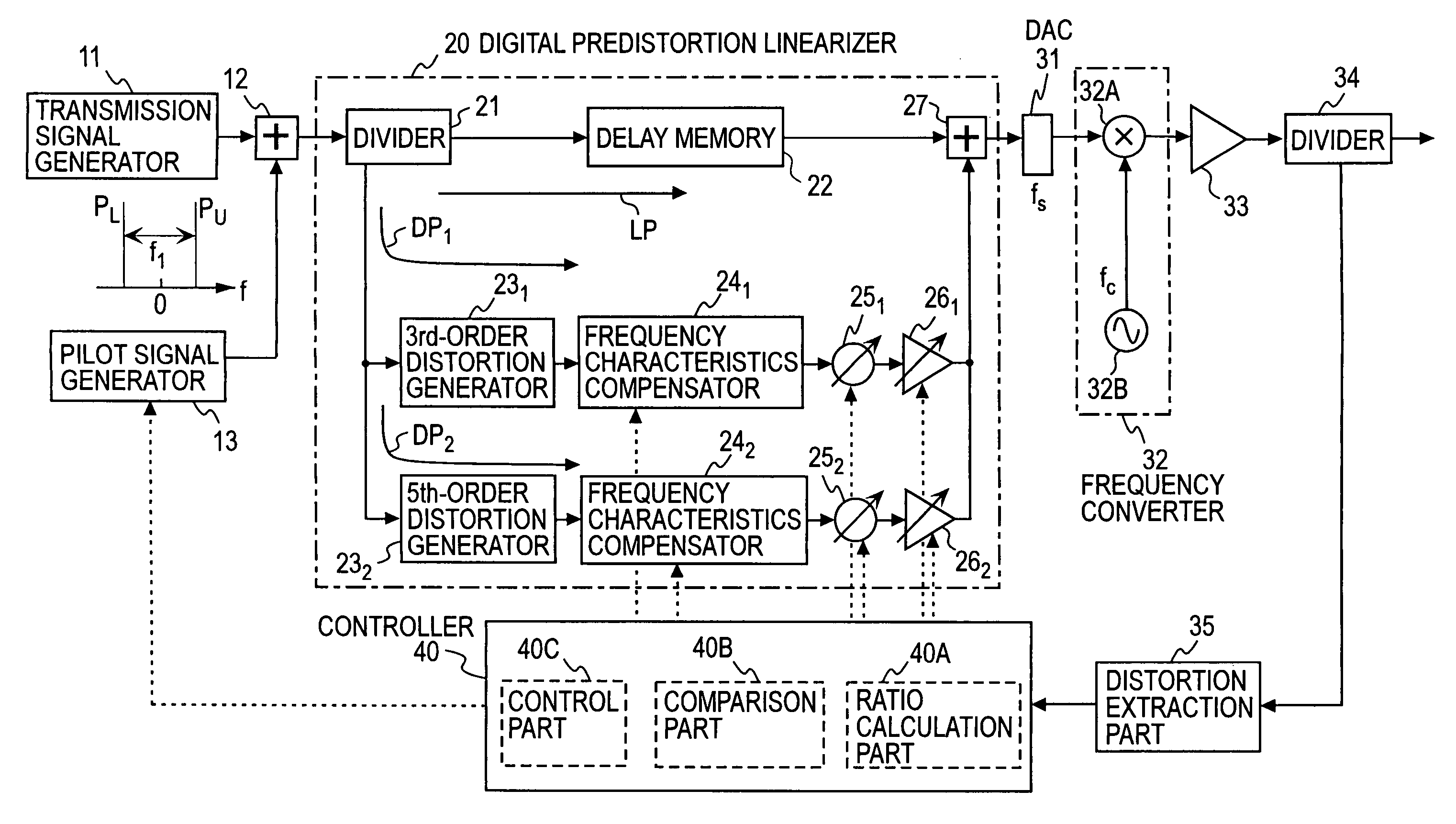
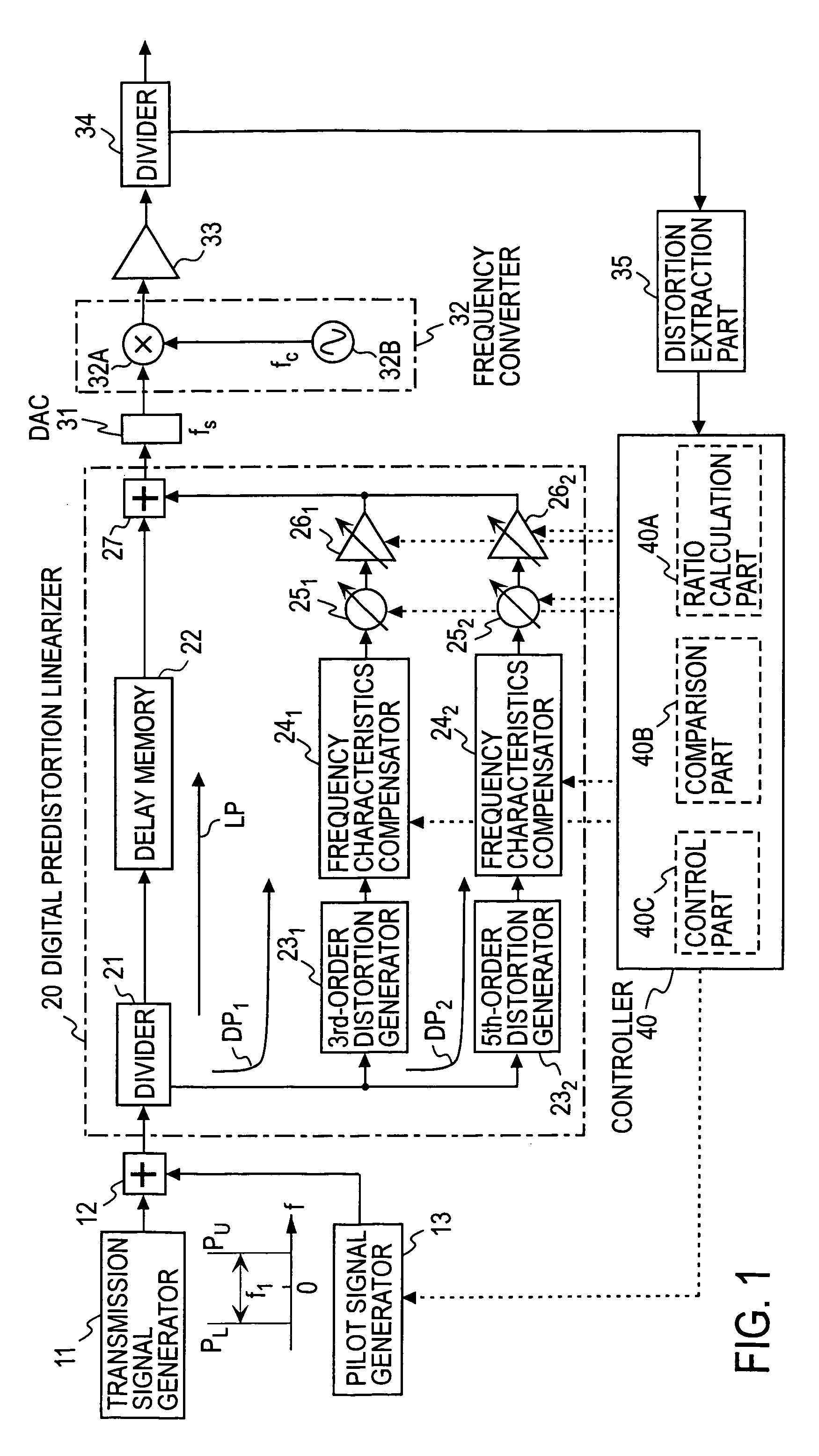
[0036]FIG. 1 illustrates in block form a basic configuration of the power series predistortion linearizer with a control means embodying the present invention. The illustrated power series predistortion linearizer is intended for compensating for 3rd- and 5th-order distortions. A transmission signal from a transmission signal generator 11 is supplied via an adder 12 to a digital predistortion linearizer 20. The predistortion linearizer 20 divides and distributes the input signal by a divider 21 to a linear signal transfer path LP including a delay memory 22, a 3rd-order distortion generation path DP1, and a 5th-order distortion generation path DP2, and adds the outputs from these paths LP, DP1 , and DP2 by an adder 27 to provide the output from the predistortion linearizer 20. In the 3rd-order distortion generation path DP1 , there are connected in series a 3rd-order distortion generator 231, a frequency characteristic compensator 241, a phase adjuster 251, and a gain adjuster 261. ...

embodiment 2

[0056]FIG. 7 illustrates in block form a second embodiment of the present invention.

[0057]In this embodiment, a 7th-order distortion generation path DP3 is added as another distortion generation path of the digital predistortion linearizer 20 in the FIG. 1 embodiment and the frequency characteristic compensator in each distortion generation path is formed by an FIR filter. The outputs from the respective distortion generation paths DP1, DP2 and DP3 are added together by adders 271 and 272, and the added output is added by the adder 27 to the output from the linear signal transfer path LP via the delay memory 22. There are further provided a low-pass filter 31F for removing aliasing from the DAC 31 output and a band pass filter 32C for removing an out-band signal from the output of the mixer 32A forming the frequency converter 32. The divider 34 is made up of a directional coupler 34A and a band pass filter 34B. The output from the divider 34 is down converted by a carrier of the fre...

embodiment 3

[0063]FIG. 9 illustrates in block form a third embodiment of the present invention. In this embodiment, denoting the frequency characteristic compensator in (2n+1)th-order distortion generation path by 24n, where n=1, 2 and 3, the FIR filter forming the frequency characteristic compensator 24n of the distortion generation path DPn of respective (2n+1)th-order in the FIG. 7 embodiment is replaced by a set of Fast Fourier Transform (FFT) 24An, frequency characteristic adjuster 24Bn and Inverse Fast Fourier Transform (IFFT) 24Cn. With this configuration for frequency characteristic control, the output signal from the distortion generator 23n is converted by FFT 24An to a frequency-domain signal, then the signal is multiplied by the frequency characteristic adjuster 24Bn by coefficients of desired frequency characteristics, and the multiplied signal is inversely converted by IFFT 24Cn to a time-domain signal.

[0064]The 3rd-order distortion component controller 421 of the controller 40 co...


PUM


Abstract

A gain adjuster and a phase adjuster of a distortion generation path are set so that an extracted distortion component becomes small, the extracted component is compared with a reference value. When an upper-frequency distortion component of a pilot signal is larger than the reference value, the gain and phase of a frequency characteristic compensator of the distortion generation path are controlled so that the upper-frequency distortion component of the pilot signal becomes smaller than a value preset in the controller. When a lower-frequency distortion component of the pilot signal is larger than a reference value, the gain and phase of the frequency characteristic compensator of the distortion generation path are controlled so that the lower-frequency distortion component of the pilot signal becomes smaller than a value preset in the controller.

Description

TECHNICAL FIELD[0001]The present invention relates to linearization of a power amplifier for use in radio communication transmitters.BACKGROUND ART[0002]One of known methods of nonlinear compensation for a power amplifier is a predistortion method. The predistortion method adds a distortion component in advance to the input signal so as to cancel the distortion component that occurs in a power amplifier. In this specification the distortion component that is added by the predistortion method will hereinafter be referred to as a compensation signal. An ideal compensation signal is set to be equal in level to but 180° out of phase with the distortion component that is actually created by the power amplifier. The amount of compensation for distortion by the predistortion method depends on accuracies of the amplitude and phase of the compensation signal. For example, when the input-output characteristics of the power amplifier are formulated by a power series model, a compensation signa...

Claims


Application Information

Patent Timeline
Patent Type & Authority Patents(United States)
IPC IPC(8): H03F3/66H03F1/00H03F1/32H03F3/24H04B1/04
CPCH03F1/3247H03F1/3258H03F2201/3209A47J43/288
Inventor MIZUTA, SHINJISUZUKI, YASUNORI
Owner NTT DOCOMO INC
Why Eureka
Try Eureka