Apparatus and methods using acoustic telemetry for intrabody communications

a technology of intrabody communication and acoustic telemetry, which is applied in the direction of telemetry patient monitoring, flow monitors, sensors, etc., can solve the problems of not being able to communicate effectively with implants located deep within the body, rf devices may also require substantial electrical power, and penetrate a few millimeters, so as to facilitate intrabody communication

Active Publication Date: 2007-04-03
REMON MEDICAL TECH
View PDF33 Cites 296 Cited by
  • Summary
  • Abstract
  • Description
  • Claims
  • Application Information

AI Technical Summary

Benefits of technology

[0023]Thus, the systems and methods of the present invention may facilitate intrabody communication between two implants using acoustic telemetry, where one of the implants may serve as a master implant, controlling the operation of the second (or additional) implant. The first implant, via an acoustic command, may switch the second passive implant to an active status, whereupon it may perform a series of predefined activities including therapeutic and / or diagnostic functions. At any stage of its operation, the second implant may communicate with the first implant, i.e., transmitting and / or receiving information. For example, the second implant may activate drugs using photodynamic therapy or ultrasonic activation or control opening of a drug reservoir.

Problems solved by technology

RF energy, however, may only penetrate a few millimeters within a body, because of the body's dielectric nature, and therefore may not be able to communicate effectively with an implant that is located deep within the body.
RF devices may also require substantial electrical power, because the devices generally consume electrical energy even when in a dormant state.
In addition, although an RF transmitter may be able to induce a current within an implant, the implant's receiving antenna, generally a low impedance coil, may generate a voltage that is too low to provide a reliable switching mechanism.
The presence of external magnetic fields encountered by the patient during normal activity, however, may expose the patient to the risk of false positives, i.e., accidental activation or deactivation of the implant.
Furthermore, external electromagnetic systems may be cumbersome and may not be able to effectively transfer coded information to an implant.

Method used


Image

  • Apparatus and methods using acoustic telemetry for intrabody communications
  • Apparatus and methods using acoustic telemetry for intrabody communications
  • Apparatus and methods using acoustic telemetry for intrabody communications

Examples


Embodiment Construction

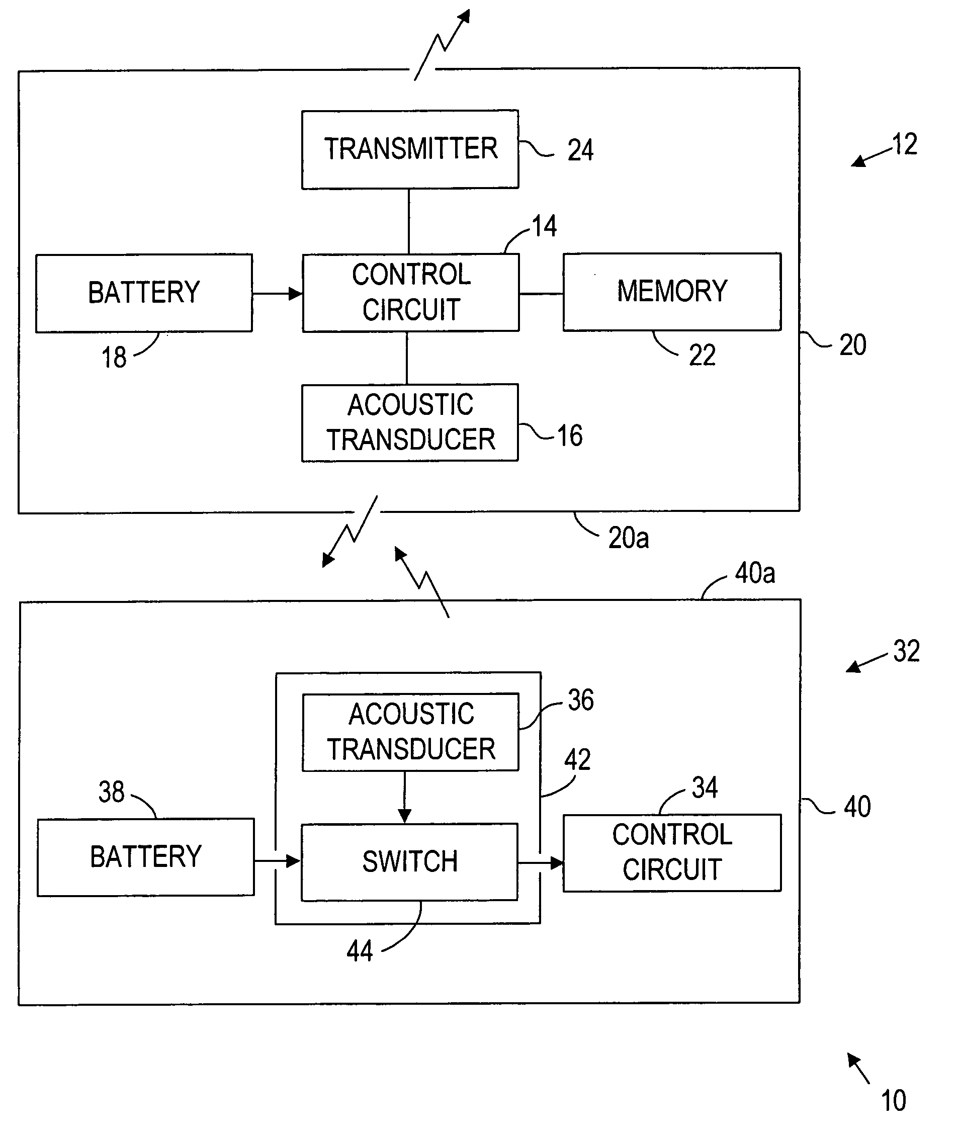
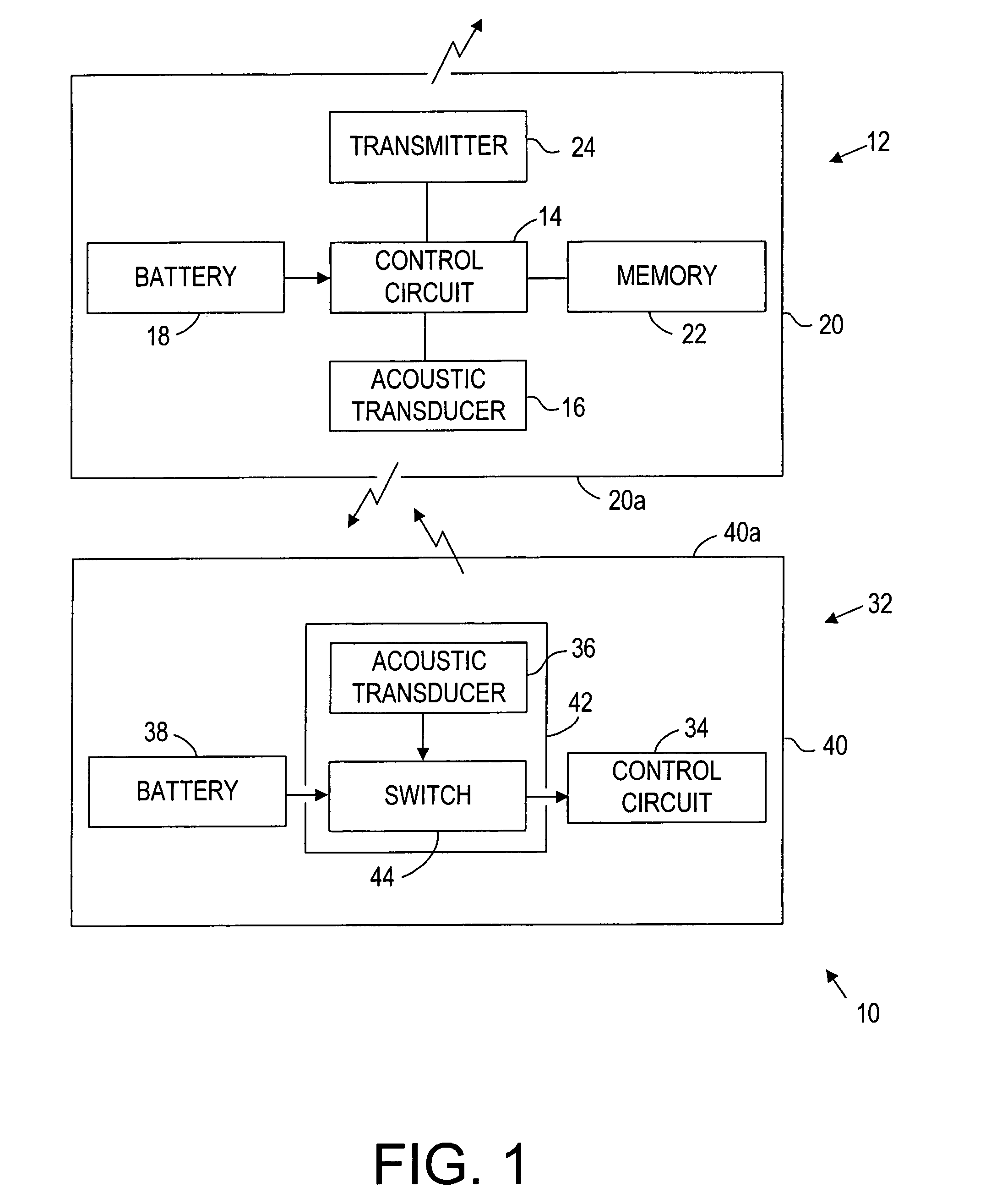
[0034]Turning to the drawings, FIG. 1 shows a first preferred embodiment of a system 10 for intrabody communication between two or more implants implanted within a patient's body (not shown). Generally, the system 10 includes a first implant 12 (also called the control or master implant), and a second implant 32 (also called the dormant or slave implant). Optionally, the system 10 may include additional implants (not shown), e.g., one or more additional dormant or slave implants, similar to the second implant 32, with which the control implant 12 may communicate, as described below.

[0035]I. Control Implant

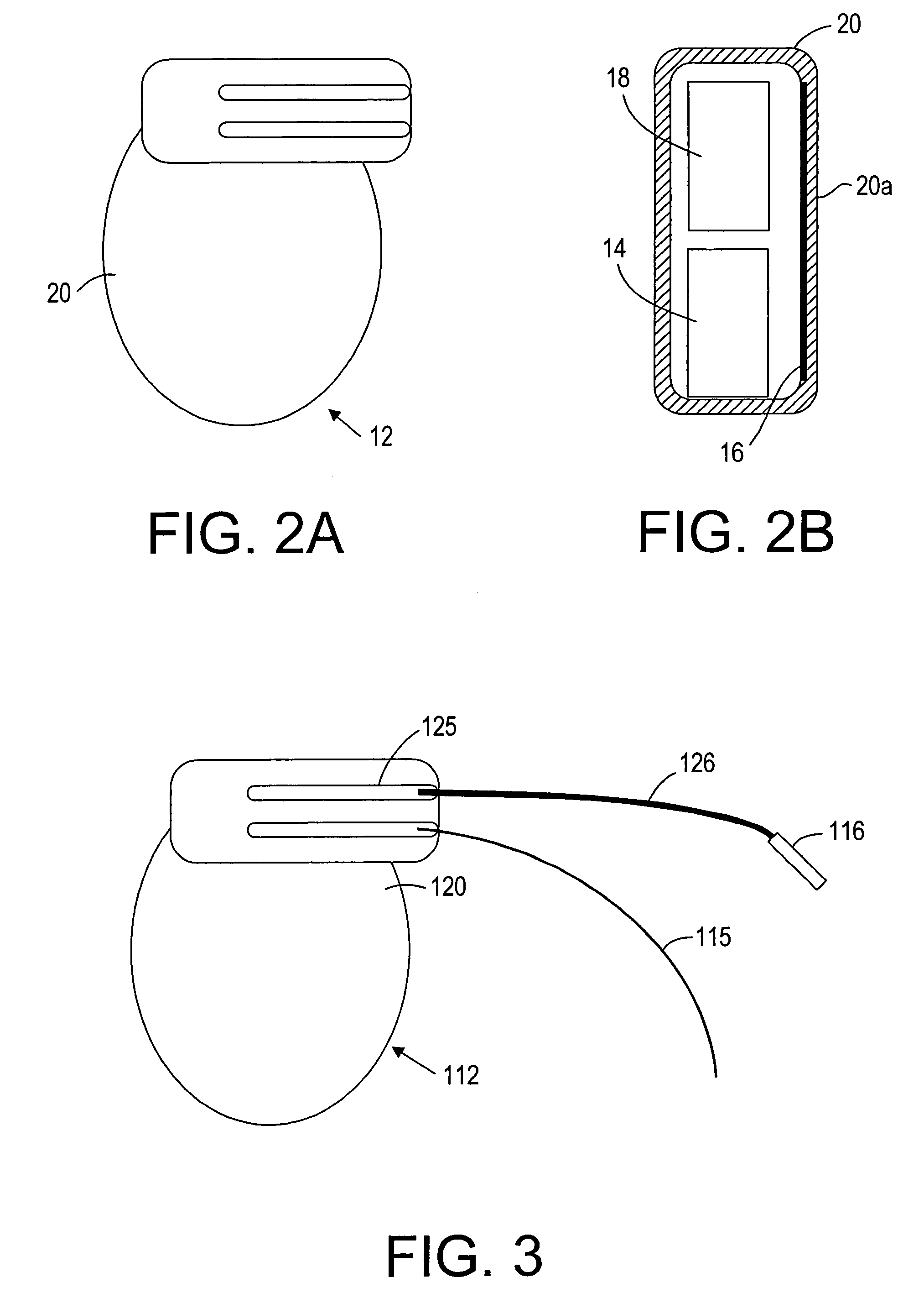
[0036]The control implant 12 may include a plurality of components, e.g., electrical circuitry 14, an acoustic transducer 16, and / or an energy source 18, provided within a box or casing 20. The casing 20, e.g., formed from titanium and the like, may be substantially sealed, and preferably hermetically sealed to substantially isolate the components of the control implant 12 from out...


PUM


Abstract

Systems and methods provide intrabody communication using acoustic telemetry. The system includes a first or control implant including a first acoustic transducer, and a second implant including a switch and a second acoustic transducer coupled to the switch. The second acoustic transducer receives acoustic signals from the first acoustic transducer for closing the switch to activate the second implant. The second implant may include a sensor for measuring a physiological parameter that is transmitted using acoustic signals including the physiological data to the first implant. For example, the second implant may measure pressure in the patient's heart that may be used by the first implant to control a pacemaker. Alternatively, the second implant may blood sugar concentration that may be used by the first implant to control an insulin pump. Alternatively, the first implant may store and transfer the data to an external device for monitoring the patient.

Description

INTRODUCTION[0001]The present invention relates generally to devices for implantation within a patient's body, and more particularly to systems and methods for communication within a patient's body using acoustic telemetry, e.g., using one implant within a body to activate, deactivate, and / or otherwise control one or more additional implants located within the body that monitor physiological conditions and / or provide therapeutic functions.BACKGROUND OF THE INVENTION[0002]Devices are known that may be implanted within a patient's body to monitor one or more physiological conditions and / or to provide therapeutic functions. For example, sensors or transducers may be located deep within the body for monitoring a variety of properties, such as temperature, pressure, strain, fluid flow, chemical properties, electrical properties, magnetic properties, and the like. In addition, devices may be implanted that perform one or more therapeutic functions, such as drug delivery, defibrillation, e...

Claims


Application Information

Patent Timeline
Patent Type & Authority Patents(United States)
IPC IPC(8): A61B5/02A61N1/00A61B5/00A61B5/0215A61B5/026A61B5/03A61B17/00A61K9/22A61M5/142A61M5/172A61N1/372
CPCA61B5/0028A61B5/0031A61B5/0215A61B5/14532A61B5/4839A61M5/14276A61M5/1723A61N1/37217A61N1/37288A61B5/0008A61B5/026A61B5/031A61B5/14539A61B2017/00026A61B2560/0214A61B2560/0257A61M2205/3507A61N1/378
Inventor PENNER, AVIDORON, EYAL
Owner REMON MEDICAL TECH
Why Eureka
Try Eureka