
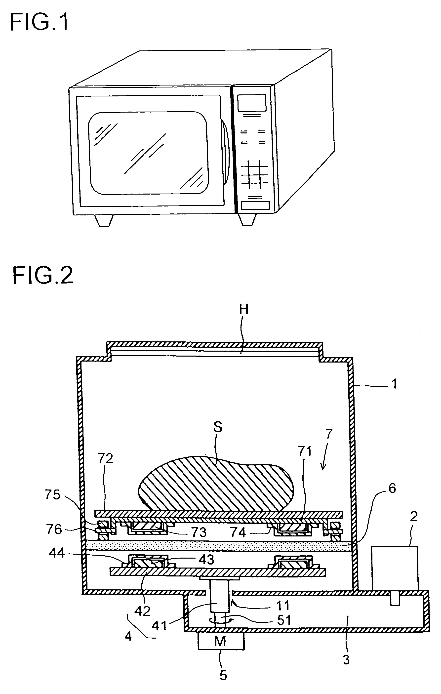
High-frequency heating apparatus

a heating apparatus and high-frequency technology, applied in electrical equipment, microwave heating, electric/magnetic/electromagnetic heating, etc., can solve the problems of increasing the power consumption of the heater, the heating duration cannot be shortened, and the heating efficiency of the heater is increased, so as to achieve delicately controlled uniform heating and enhance the heating efficiency of the grill heating and oven heating

Inactive Publication Date: 2007-04-03
SHARP KK
View PDF13 Cites 38 Cited by
  • Summary
  • Abstract
  • Description
  • Claims
  • Application Information

AI Technical Summary

Benefits of technology

[0014]In view of the conventionally experienced problems mentioned above, it is an object of the present invention to provide an antenna-type microwave oven that, while maintaining the advantages it has conventionally had, offers enhanced heating efficiency in grill heating and oven heating and permits delicately controlled uniform heating.
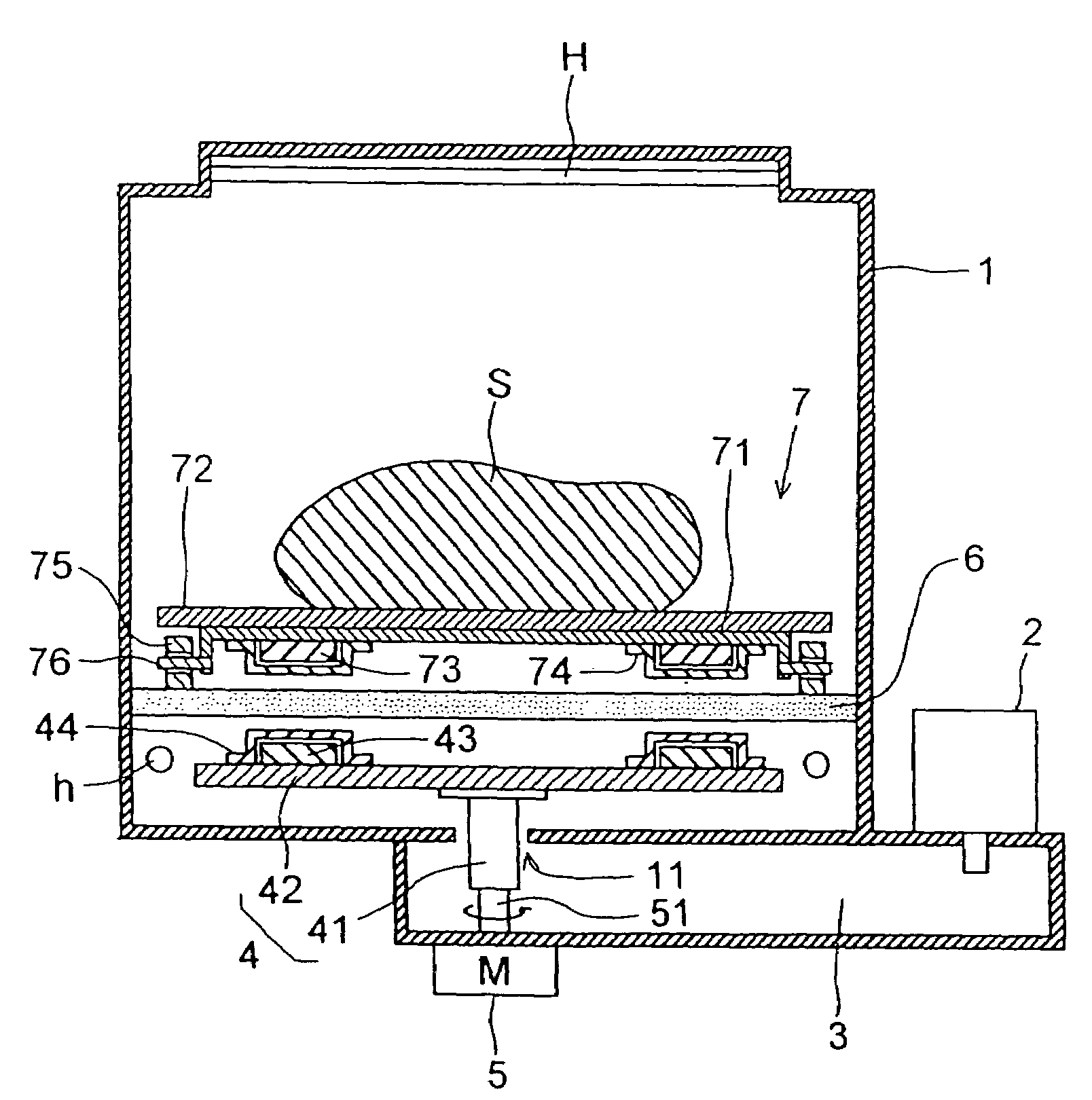
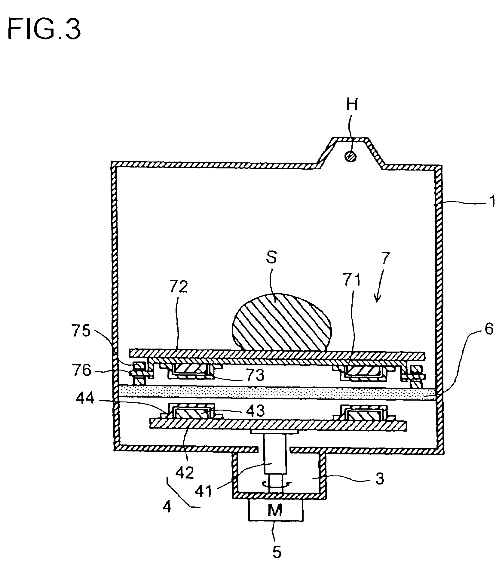
[0017]Here, from the viewpoint of permitting rotatable placement of the heating target in an antenna-type microwave oven, enhancing the heating efficiency in grill heating and oven heating, and permitting uniform high-frequency heating of the heating target, it is preferable to use, as the rotary member, a rotary stage provided with: a support member having a plurality of rollers and magnets; and a table that is supported on the support member and on which the heating target is placed. Moreover, to permit the table to rotate faster than the antenna, it is preferable that the table be supported on the plurality of rollers by being kept in contact therewith so that, as the rollers rotate, the table rotates.
[0019]The rotary member may be a stirring member provided in a container placed on the stage. This, while maintaining the advantage of an antenna-type microwave oven that the floor of the heating compartment has a flat surface without holes and is thus easy to clean, makes it possible to stir with the stirring member the foodstuffs put in the container placed in the heating compartment.
[0021]From the viewpoint of preventing surface contact between the radiator portion of the antenna and the bottom surface of the stage and thereby achieving smooth rotation without friction thereof, and in addition precisely controlling the distance between the radiator portion of the antenna and the bottom surface of the stage and the length over which the receiver portion of the antenna protrude into the waveguide, it is preferable to provide a restricting member on at least one of the antenna and the stage in order to restrict the movement of the antenna in the axial direction. Preferably, the antenna is composed of a cylindrical receiver portion and a substantially disk-shaped radiator portion fitted at the top end of the receiver portion coaxially therewith, and the restricting member is formed on the top surface of the radiator portion of the antenna at equal angular intervals in the circumferential direction.
[0022]From the viewpoint of preventing magnetic attraction between the magnet fitted on the antenna and the floor, made of a magnetic material, of the heating compartment and thereby achieving smooth rotation of the antenna, it is preferable that the side of the magnet fitted on the antenna which faces the stage be covered with a nonmagnetic member, and that the side of the same magnet which faces the floor of the heating compartment be covered with a magnetic member. Here, when the antenna is formed of a nonmagnetic member, it is preferable that the magnet be provided on the bottom surface of the antenna, and that the surface of the magnet be covered with a magnetic member. By contrast, when the antenna is formed of a magnetic member, it is preferable that the magnet be provided on the top surface of the antenna, and that the surface of the magnet be covered with a nonmagnetic member.
[0023]For the purpose of browning the heating target and for other purposes, a heater is sometimes brought close to the periphery of the antenna and operated with the antenna stationary. In this case, the magnet fitted on the antenna is locally exposed to high temperature. In general, a magnet undergoes irreversible demagnetization at high temperature. Thus, the magnet, if demagnetized at high temperature, will weaken the magnetic coupling between the antenna and the rotary member, leading to loss of rotation of the rotary member. To avoid this, it is strongly recommended to rotate the antenna when the heater is operating in order to reduce the effect of the heat generated by the heater on the magnet fitted to the antenna.

Problems solved by technology

Arranging the heater H over the entire ceiling surface, however, results in the heater H occupying a large area.
Disadvantageously, the heating duration cannot be shortened without increasing the power consumption by the heater.
Moreover, the method using an antenna, just because it keeps the heating target at rest, occasionally produces unsatisfactory results in the preparation of, for example, egg dishes such as chawan-mushi, a Japanese egg-based pot-steamed hotchpotch, which require delicately controlled uniform heating.
On the other hand, in a conventional antenna-type microwave oven, there is provided no mechanism for driving a stirring wheel.
This makes it impossible to add thereto a function of automatic stirring.

Method used


Image

  • High-frequency heating apparatus
  • High-frequency heating apparatus
  • High-frequency heating apparatus

Examples


first embodiment

[0109]First, the first embodiment will be described with reference to FIG. 28. If, in step S105 in FIG. 27, the heating means is found not to be high-frequency heating (i.e., if it is found to be heater heating), then the flow proceeds to step S110 in FIG. 28. In this step, the antenna stop time T1, which has thus far been rotating, is set. Next, in step S120, a stop timer is reset, and then, in step S130, the stop timer is started to count time. The antenna stop time T1 may be a fixed duration that is determined in advance, or may be a function of the set heating duration T0 or of the actual heating duration and the actual operation duration of the lower heater. By setting the antenna stop time T1 to be a function of the set heating duration T0 or the like, it is possible, when the set heating duration T0 is short, to shorten the antenna stop time T1 accordingly. This helps eliminate unnecessary power consumption. FIG. 31 shows an example where the stop time T1 is set to be a funct...

second embodiment

[0112]Next, the second embodiment will be described with reference to FIG. 29. If, in step S105 in FIG. 27 described earlier, the heating means is found not to be high-frequency heating (i.e., if it is found to be heater heating), then the flow proceeds to step S210 in FIG. 29. In this step, the antenna stop temperature S1 is set. Next, in step S220, the heating compartment temperature TS is sensed, and then the flow proceeds to step S230. In this step, whether or not the door is open is checked. If the door is found to be open, then, in step S240, the fourth relay switch SW4 is turned off to stop the rotation of the antenna 4. Then, the flow returns to step S230, where whether or not the door is open is checked again. So long as the door is found to be open, the operations in steps S230 and S240 are repeated. Thereafter, when the door 15 is found not to be open, the flow proceeds to step S250, where the fourth relay switch SW4 is turned on to rotate the antenna 4.

[0113]Next, in ste...

third embodiment

[0114]Lastly, the third embodiment will be described with reference to FIG. 30. If, in step S105 in FIG. 27 described earlier, the heating means is found not to be high-frequency heating (i.e., if it is found to be heater heating), then the flow proceeds to step S310 in FIG. 30. In this step, the antenna stop time T1 is set. Next, in step S320, the stop timer is reset, and then the flow proceeds to step S330, where the stop timer is started to count time. Next, in step S340, whether or not the door is open is checked. If the door is found to be open, then, in step S341, whether or not the rotary stage 7 is being used is checked. If the rotary stage 7 is found to be used, then, irrespective of whether or not the timer has reached the antenna stop time T1, in step S350, the fourth relay switch SW4 is turned off to stop the rotation of the antenna 4. Then, the flow returns to step S340, where whether or not the door is open is checked again. So long as the door is found to be open and ...


PUM


Abstract

A high-frequency heating apparatus comprises a heating chamber, a high-frequency generator, a waveguide, an antenna, a motor for rotating the antenna, and a stage (6) provided above and near the antenna to partition the heating chamber and made of dielectric. A rotary base on which an object to be heated is mounted is provided on the stage. A first magnet is provided to the antenna. A second magnet is provided on the rotary base at a place corresponding to the first magnet on the rotary base. By utilizing the magnetic coupling between the first and second magnets, the rotary base is rotated in synchronism with the rotation of the antenna. While maintaining the advantages of conventional antenna high-frequency heating apparatuses, the heating efficiency by grill heating or oven heating is enhanced, and minute heating uniformness is achieved.

Description

TECHNICAL FIELD [0001]The present invention relates to a high-frequency heating apparatus (hereinafter also referred to as a “microwave oven”), and more particularly to an antenna-type high-frequency heating apparatus.BACKGROUND ART [0002]Roughly speaking, uniform heating inside the heating compartment of a microwave oven is achieved by the use of a turntable, stirrer, or antenna. Now, a brief description will be given of how uniform heating is achieved by the use of each of these. Where a turntable is used, a heating target is placed on the turntable provided on the floor of the heating compartment, and the turntable is rotated. Thus, the high-frequency wave radiated into the heating compartment through an opening formed on a side wall surface or the ceiling surface thereof strikes the heating target uniformly from all directions, thereby heating it. This is the method that is currently most commonly used in microwave ovens. FIGS. 32 and 33 are a sectional view and a perspective vi...

Claims


Application Information

Patent Timeline
Patent Type & Authority Patents(United States)
IPC IPC(8): H05B6/74H05B6/72H05B6/80
CPCH05B6/6411H05B6/72H05B6/725
Inventor KANEKO, FUMINORIKITAYAMA, HIROKIYAMAMOTO, YOSHIKAZUANDOH, YUZI
Owner SHARP KK
Learn More