Multi-stage amplifier with switching circuitry

a switching circuit and amplifier technology, applied in the direction of amplifiers, amplifiers, switching capacitors, etc., can solve the problems of denying any opportunity to short or otherwise reset the operational amplifier input, parasitic capacitance can build up undesired charges, and save cost, area and power, so as to reduce parasitic charges and parasitic charges

Inactive Publication Date: 2007-04-03
RE SECURED NETWORKS LLC
View PDF7 Cites 15 Cited by
  • Summary
  • Abstract
  • Description
  • Claims
  • Application Information

AI Technical Summary

Benefits of technology

[0019]A method embodiment of the technology includes operating the first stage of the amplifier circuit; operating the second stage of the amplifier circuit; and substantially reducing parasitic charge at one or more of the signal inputs of the operational amplifier. One example of substantially reducing parasitic charge includes: during one of the stages of the amplifier circuit, storing charge from one or more of the signal inputs of the operational amplifier; and during another of the stages of the amplifier circuit, discharging the stored charge to the one or more of the signal inputs of the operational amplifier. During operation of the first stage of the amplifier circuit, a first signal is provided to one of the signal inputs of the operational amplifier, and a first capacitive value is provided as the feedback of the operational amplifier. During operation of the second stage of the amplifier circuit, a second signal is provided to one of the signal inputs of the operational amplifier, and a second capacitive value is provided as the feedback of the operational amplifier.

Problems solved by technology

Because the different stages share the same operational amplifier, this amplifier design saves cost, area, and power in comparison with a cascaded design that has separate operational amplifiers for different stages of an amplifier circuit.
However, in multi-stage amplifier circuits that share the same operational amplifier among multiple stages, the operational amplifier may be in continuous or near-continuous use, denying any opportunity to short or otherwise reset the operational amplifier input.
As a result, the parasitic capacitance can build up undesired charge during operation of the amplifier circuit, distorting the output of the amplifier circuit.
If the amplifier circuit is part of a programmable gain amplifier that processes data from an image sensor array, then about one pixel of data from the image sensor array is improperly processed by the amplifier circuit.

Method used


Image

  • Multi-stage amplifier with switching circuitry
  • Multi-stage amplifier with switching circuitry
  • Multi-stage amplifier with switching circuitry

Examples


Embodiment Construction

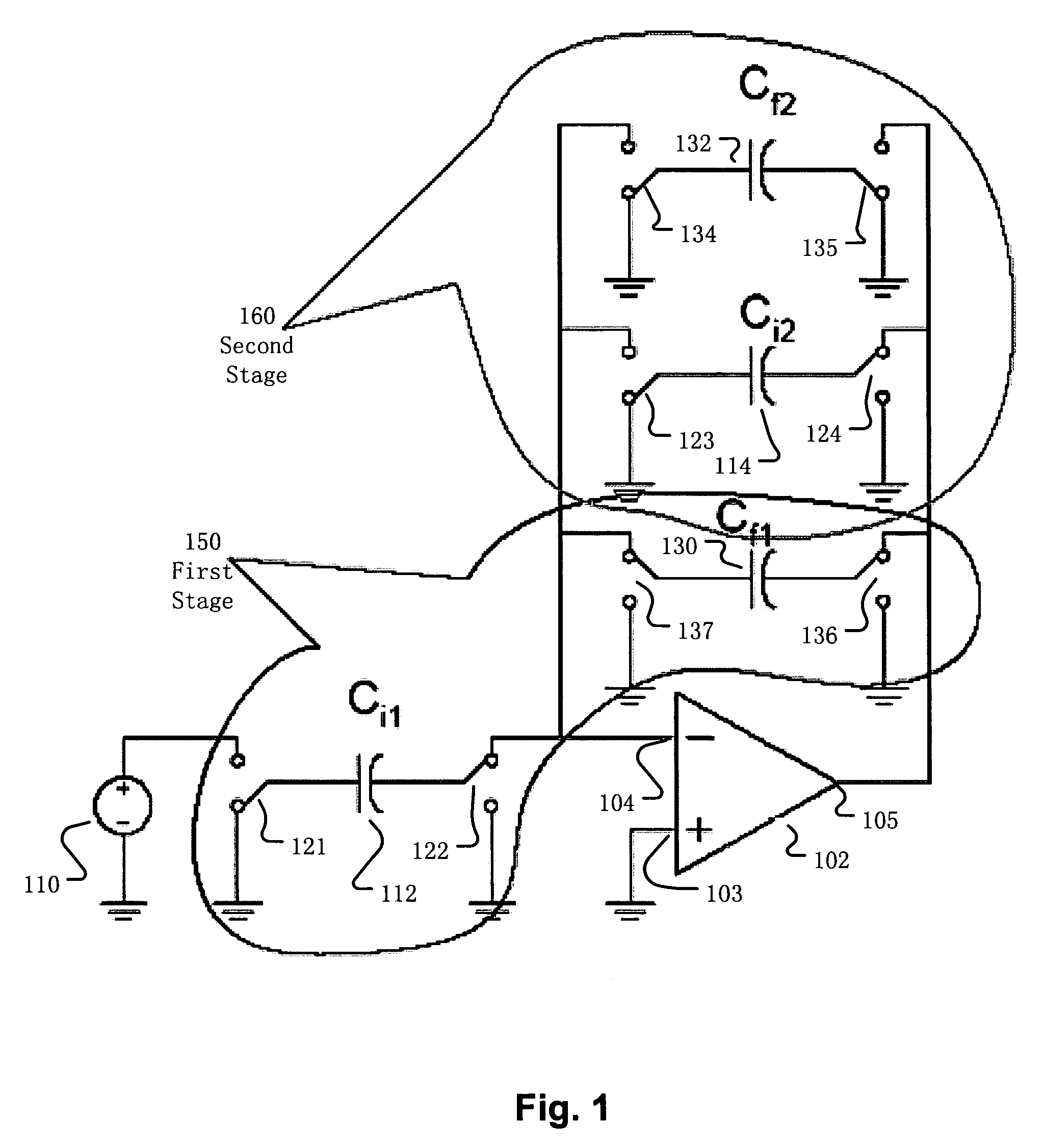
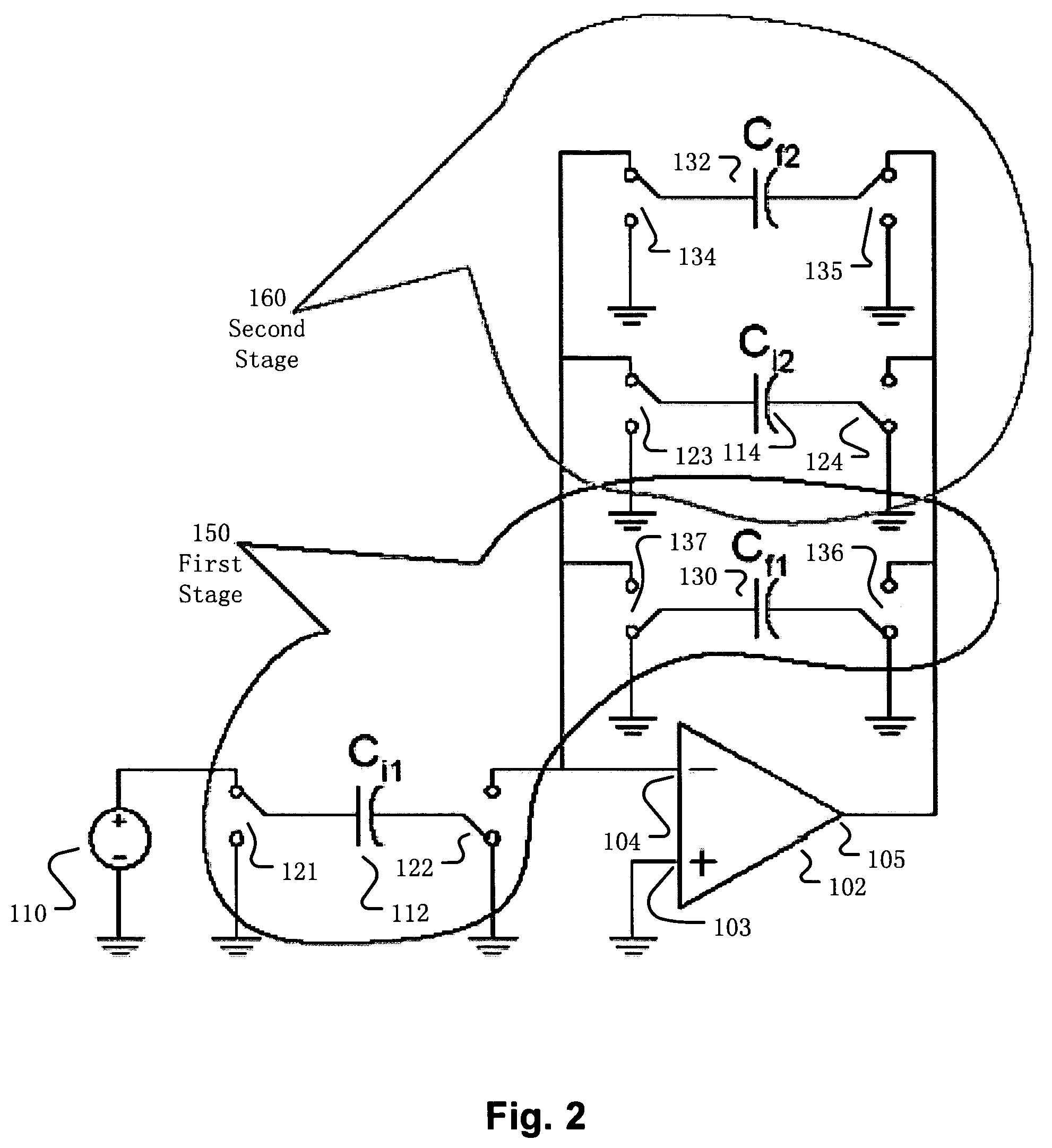
[0035]The technology relates to a multi-stage amplifier that shares an operational amplifier among multiple stages. Embodiments include switching circuitry to substantially reduce parasitic charge at the operational amplifier input stored by the parasitic capacitance.

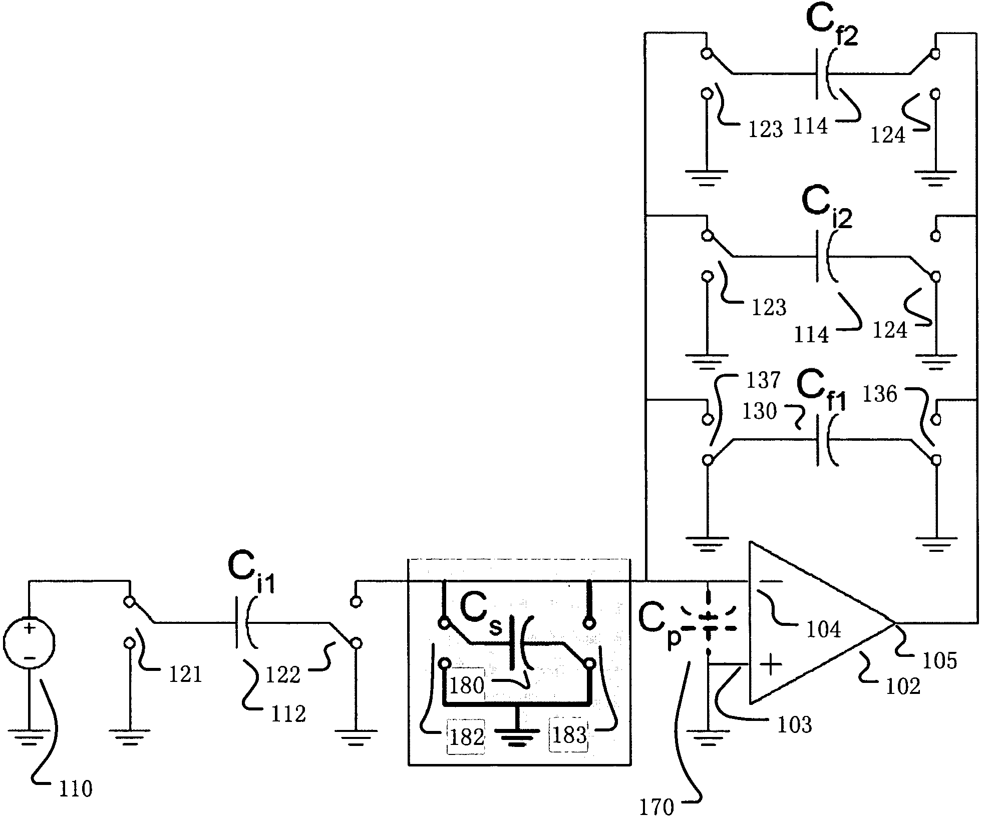
[0036]FIG. 6 is a diagram of the multi-stage amplifier circuit showing the parasitic capacitance across inputs of the operational amplifier and switching circuitry that switches polarities of the capacitor coupled to the inverting input of the operational amplifier. Depending on the particular stage of the multi-stage amplifier, switches 182 and 183 change position to change the polarity of the switched capacitor 180 that is coupled to the operational amplifier inverting input. The capacitance value of the switched capacitor 180 is determined empirically via simulation.

[0037]FIGS. 7A, 7B, and 7C show the clock signal, the input signal, and the output signal of the amplifier circuit without the capacitor polarity switchi...


PUM


Abstract

Disclosed are a multi-stage amplifier circuit, a method of operating a multi-stage amplifier circuit, and a device with the multi-stage amplifier circuit. The amplifier circuit technology includes an operational amplifier shared among multiple stages and switching circuitry. The various switching circuitry switches among elements to provide different input signals and different feedback to the shared operational amplifier at the different stages of operation of the amplifier circuit. The various switching circuitry also stores and discharges charge at one or more operational amplifier inputs.

Description

BACKGROUND[0001]1. Field[0002]The technology relates to multi-stage switched capacitors.[0003]2. Description of Related Art[0004]FIGS. 1 and 2 are diagrams of a multi-stage amplifier circuit operating in different stages, the first stage 150 and the second stage 160. Although the boundaries of first stage 150 and the second stage 160 are drawn to exclude the operational amplifier 102 for clarity of distinguishing whether particular circuitry external to the operational amplifier belongs to a particular stage, both the first stage 150 and the second stage 160 actually include the shared operational amplifier 102. Because the different stages share the same operational amplifier, this amplifier design saves cost, area, and power in comparison with a cascaded design that has separate operational amplifiers for different stages of an amplifier circuit.[0005]FIG. 1 is a diagram of a multi-stage amplifier circuit operating in the first stage. The operational amplifier 102 includes a groun...

Claims


Application Information

Patent Timeline
Patent Type & Authority Patents(United States)
IPC IPC(8): H03F1/02
CPCH03F3/005
Inventor LUO, JAIFUSUNDARARAMAN, RAJAGOPALTAN, MEHMET ALI
Owner RE SECURED NETWORKS LLC
Why Eureka
Try Eureka