Digitally-controlled reference oscillators

a reference oscillator and digital control technology, applied in the field of oscillators, can solve the problems of general failure to meet the more demanding requirements, and achieve the effect of facilitating the reduction of the size and cost of the oscillator and high performance requirements

Inactive Publication Date: 2007-04-03
MEDIATEK INC
View PDF9 Cites 13 Cited by
  • Summary
  • Abstract
  • Description
  • Claims
  • Application Information

AI Technical Summary

Benefits of technology

[0006]The present invention is directed to reference oscillator structures that facili

Problems solved by technology

Although conventional reference oscillators have met the needs of previous wirele

Method used


Image

  • Digitally-controlled reference oscillators
  • Digitally-controlled reference oscillators
  • Digitally-controlled reference oscillators

Examples


Embodiment Construction

[0015]Varactor (voltage-variable capacitor) structures are presented below that facilitate reference oscillators which can be reduced to a small portion of an integrated circuit and which provide excellent parameter performance (e.g., monotonicity, linearity, low phase noise and low differential and integral non-linearity) so that they are useful in a variety of wireless communication structures (e.g., cellular telephones).

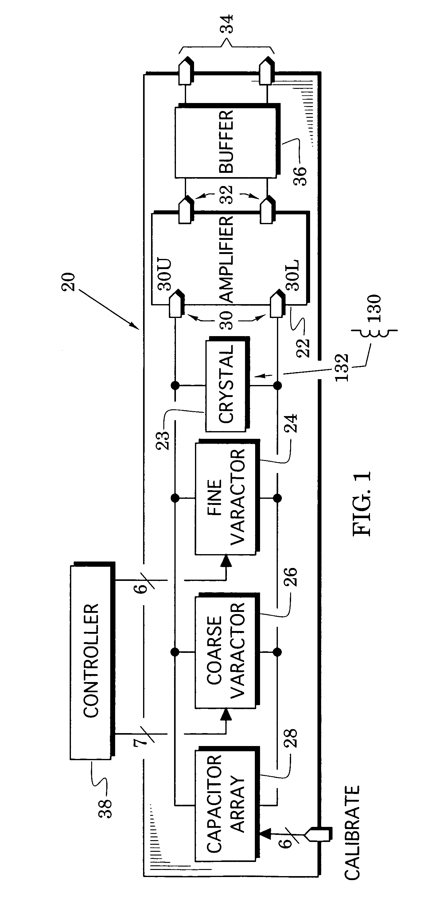
[0016]In particular, FIG. 1 illustrates a reference oscillator 20 that includes an amplifier 22, a crystal 23, a fine varactor 24, a coarse varactor 26 and a selectable capacitor array 28. The crystal, the fine and coarse varactors and the capacitor array are coupled across an input port 30 (formed by upper and lower input terminals 30U and 30L) of the amplifier 22 and an output port 32 of the amplifier is preferably coupled to an oscillator output port 34 by a buffer 36 which helps to isolate the amplifier from variable load conditions. In an embodiment of the os...


PUM


Abstract

Varactor and reference oscillator structures are provided that are particularly suited for integrated circuit fabrication and which provide excellent parameter performance (e.g., monotonicity, linearity, low phase noise and low differential and integral non-linearity) so that they are useful in a variety of wireless communication structures (e.g., cellular telephones).

Description

BACKGROUND OF THE INVENTION[0001]1. Field of the Invention[0002]The present invention relates generally to oscillators and, more particularly, to digitally-controlled reference oscillators.[0003]2. Description of the Related Art[0004]Modern wireless communication systems are used throughout the world and operate over a variety of frequency bands. For example, the global system for mobiles (GSM) has now been accepted in over 140 countries. This system includes the E-GSM 880–915 and 925–960 MHz transmitting and receiving bands for mobiles, 1710–1785 and 1805–1880 MHz transmitting and receiving bands for digital communications services (DCS), and 1850–1910 and 1930–1990 MHz transmitting and receiving bands for United States Personal Communications Services (PCS).[0005]Components of these wireless systems (e.g., cellular telephones) require reference oscillators that can provide demanding technical performance (e.g., high stability, low phase noise and linear response to a tuning potent...

Claims


Application Information

Patent Timeline
IPC IPC(8): H03B5/12
CPCH03B5/1228H03B5/1215H03B5/1243H03B5/1265H03B2200/0048H03B2201/0208
Inventor GOLDFARB, MARC E.
Owner MEDIATEK INC
Why Eureka
Try Eureka