Ion-generating component, ion-generating unit, and ion-generating apparatus

a technology of ion-generating components and ion-generating units, which is applied in the direction of corona discharge, ventilation systems, heating types, etc., can solve the problems of difficult selective generation of negative ions, increased production costs of ion-generating apparatus b>110/b>, and complicated power supply circuits and insulating structures, etc., to achieve easy production of intense electric fields, small and low-cost ion-generating units, and easy concentration

Active Publication Date: 2007-04-03
MURATA MFG CO LTD
View PDF12 Cites 3 Cited by
  • Summary
  • Abstract
  • Description
  • Claims
  • Application Information

AI Technical Summary

Benefits of technology

[0011]Since the wire electrode has a small diameter of about 100 μm or less, electrons easily concentrate at the leading end thereof, and an intense electric field is easily produced.
[0013]The above-described structures allow the wire electrode and the ground electrode to be arranged two-dimensionally, and the thickness of the ion-generating component can be reduced.
[0014]Preferably, the ground electrode is disposed substantially perpendicularly to the longitudinal direction of the wire electrode. The above-described structure increases the flexibility in arranging the wire electrode and the ground electrode.
[0015]Preferably, a surface of the ground electrode is covered with an insulating film. This can reduce the generation of ozone without substantially changing the number of generated negative ions. Preferably, the ground electrode is made of a resistor such as a ruthenium oxide or carbon resistor. This is because the resistor can reduce the dangers of heat generation and firing due to short-circuiting, for example, even when the wire electrode touches the ground electrode. Especially, ruthenium oxide is the optimum material because it does not cause migration even when an intense electric field is applied thereto.
[0019]The above-described features make it possible to obtain a small and low-cost ion-generating unit or ion-generating apparatus.
[0020]Since the ion-generating component of various preferred embodiments of the present invention uses a thin wire electrode having a diameter of about 100 μm or less, electrons easily concentrate at the leading end of the wire electrode, and an intense electric field is easily produced. Therefore, negative ions can be generated by the application of a voltage lower than before. As a result, it is possible to obtain a small and low-cost ion-generating unit or ion-generating apparatus.

Problems solved by technology

For this reason, the power supply circuit and the insulating structure are complicated, and the production cost of the ion-generating apparatus 110 is increased.
Furthermore, when a high voltage of −5 kV to −7 kV is applied to the discharging electrode 112, ozone is incidentally generated, and therefore, it is impossible to selectively generate only negative ions.

Method used


Image

  • Ion-generating component, ion-generating unit, and ion-generating apparatus
  • Ion-generating component, ion-generating unit, and ion-generating apparatus
  • Ion-generating component, ion-generating unit, and ion-generating apparatus

Examples


Embodiment Construction

[0030]An ion-generating component, an ion-generating unit, and an ion-generating apparatus according to various preferred embodiments of the present invention will be described below with reference to the attached drawings.

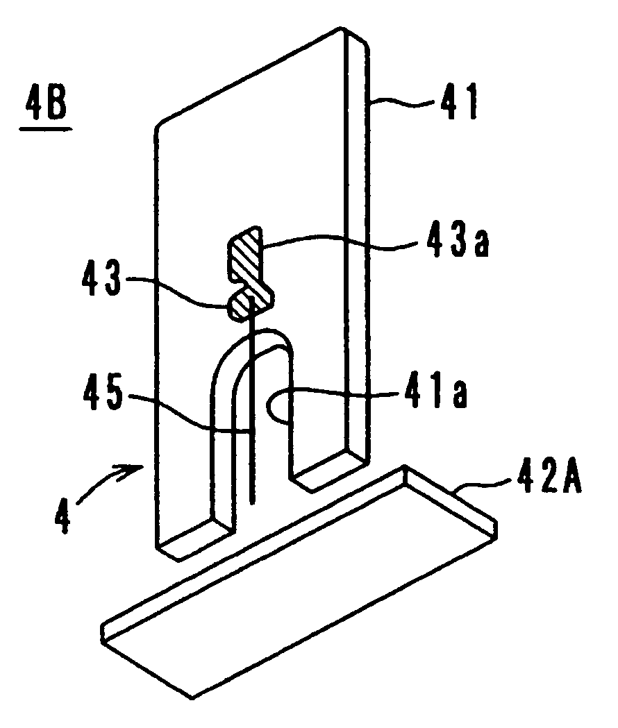
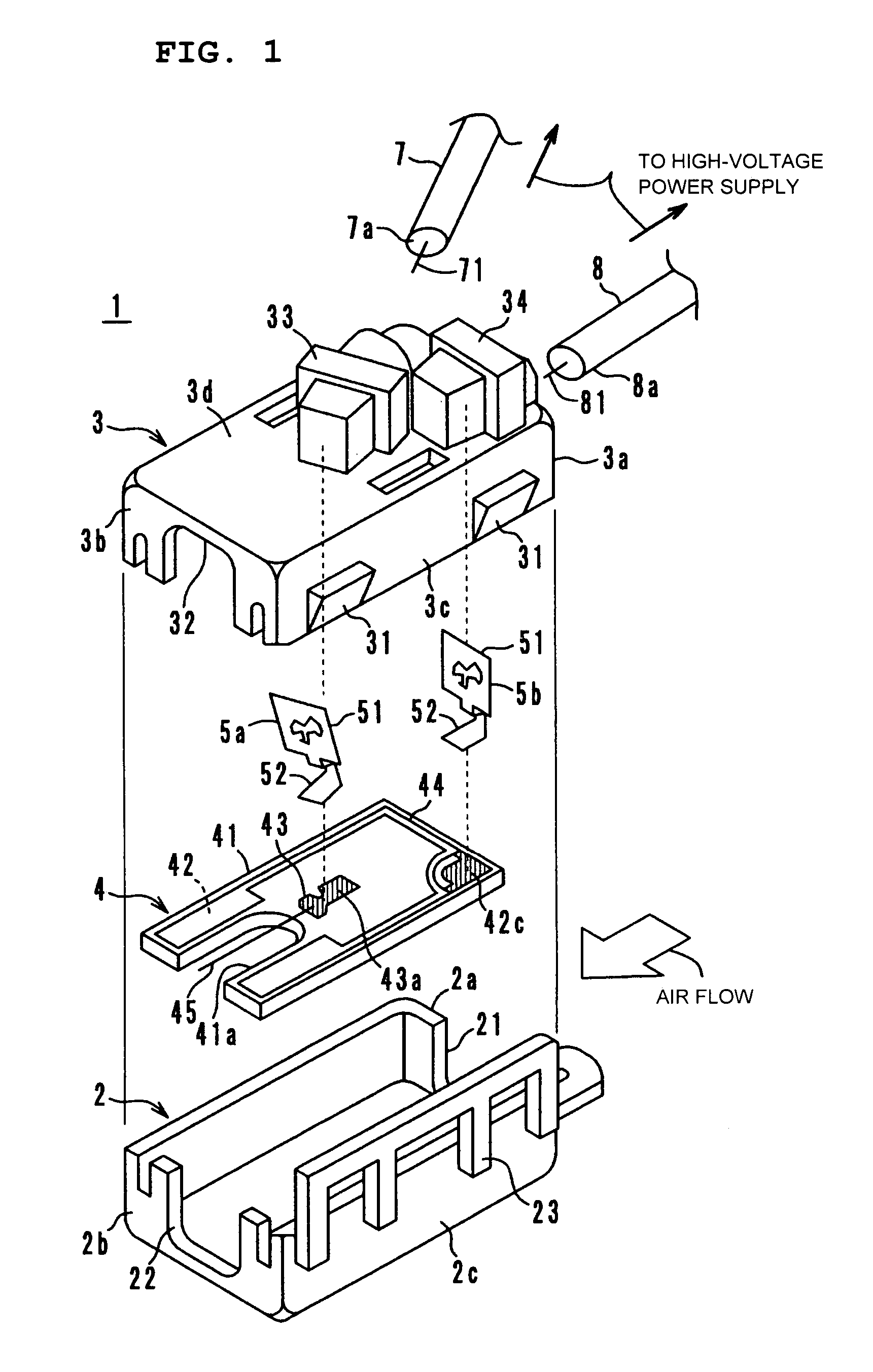
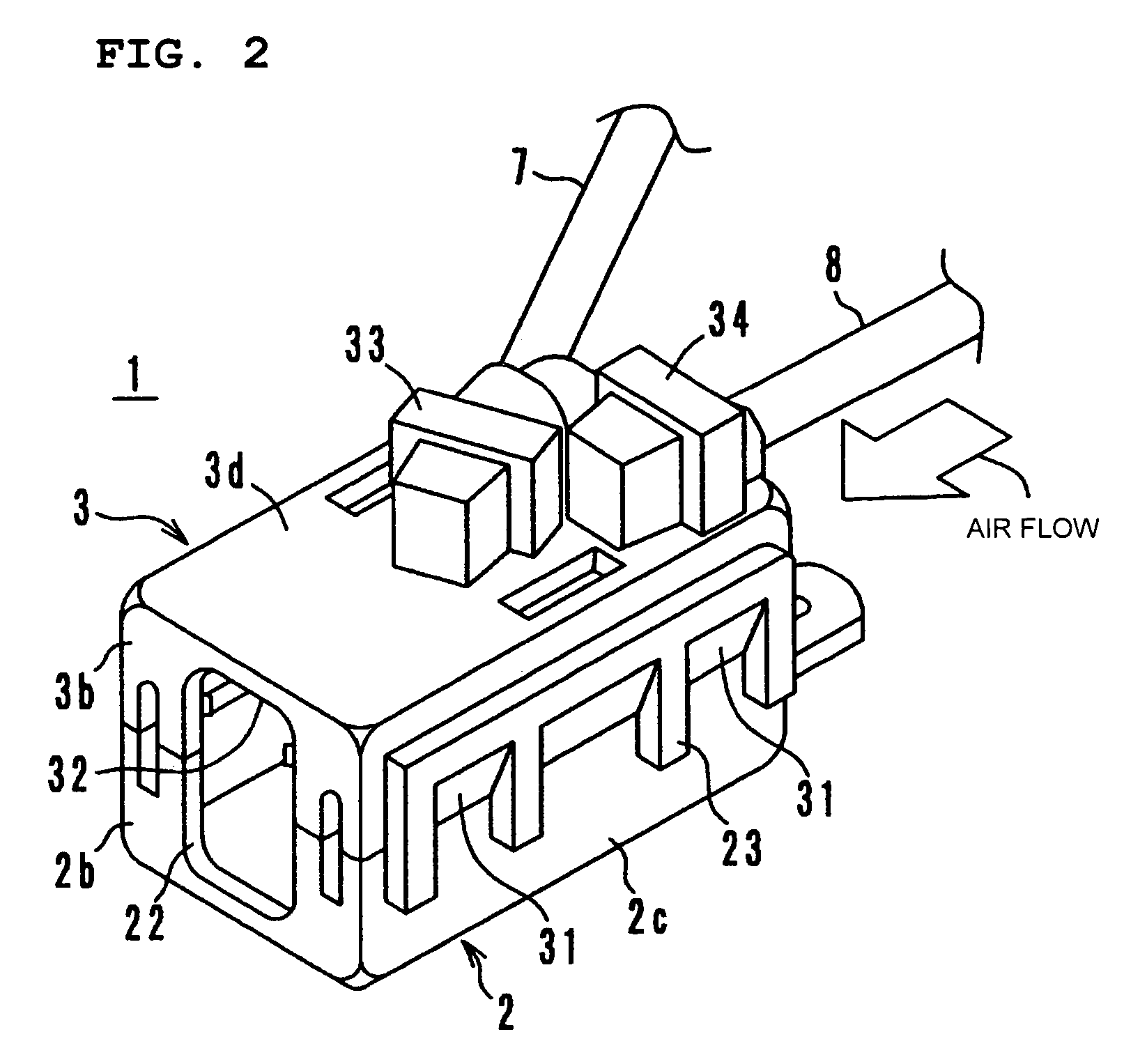
[0031]FIG. 1 is an exploded perspective view of an ion-generating apparatus 1 according to a preferred embodiment of the present invention, and FIG. 2 is an external perspective view thereof. As shown in FIG. 1, the ion-generating apparatus 1 preferably includes a lower resin case 2, an upper resin case 3, an ion-generating component 4, first and second terminals 5a and 5b made of metal, a high-voltage lead wire 7, a ground lead wire 8, and a high-voltage power supply. The lower resin case 2, the upper resin case 3, the ion-generating component 4, the first terminal 5a, and the second terminal 5b constitute an ion-generating unit.

[0032]The lower resin case 2 has an air inlet 21 provided in a side wall 2a at one end, and an air outlet 22 provided in a side wall 2b ...


PUM

PropertyMeasurementUnit
diameteraaaaaaaaaa
voltageaaaaaaaaaa
resistanceaaaaaaaaaa

Abstract

An ion-generating component has, on an insulating substrate, a ground electrode, a high-voltage electrode, an insulating film provided on the surface of the ground electrode, and a wire electrode. A cutout is formed by cutting out one side of the insulating substrate. The root of the wire electrode is soldered to the high-voltage electrode, and the leading end thereof is positioned near the cutout. The wire electrode is made of an ultrafine wire having a diameter of about 100 μm or less, for example, a piano wire, a tungsten wire, a stainless wire, or a titanium wire.

Description

BACKGROUND OF THE INVENTION[0001]1. Field of the Invention[0002]The present invention relates to an ion-generating component, and more particularly, to an ion-generating component used in a negative-ion generating circuit of an air cleaner or an air conditioner, and an ion-generating unit and an ion-generating apparatus including the ion-generating component.[0003]2. Description of the Related Art[0004]This type of ion-generating apparatus is disclosed in Japanese Unexamined Patent Application Publication No. 6-181087. FIG. 8 shows the ion-generating apparatus. As shown in FIG. 8, an ion-generating apparatus 110 includes a housing 120, a discharging electrode 112 mounted on the front surface of the housing 120, and a counter electrode 114. A high-voltage power supply 118 is disposed at the top of the housing 120. The high-voltage power supply 118 includes a high-voltage generating circuit that applies a high alternating voltage between the discharging electrode 112 and the counter e...

Claims


Application Information

Patent Timeline
Patent Type & Authority Patents(United States)
IPC IPC(8): H01T23/00H05F3/06A61L9/22B03C3/02B03C3/34B03C3/40B03C3/41B03C3/60B03C3/66F24F1/00F24F3/16F24F7/00H01T19/04
CPCA61L9/22F24F3/166H01T23/00F24F2003/1682F24F8/30F24F8/192Y02A50/20
Inventor KATO, SHINJISAKO, YOSHIHIRO
Owner MURATA MFG CO LTD
Why Eureka
Try Eureka